

The Mach-Zehnder modulator is a type of optical modulator used for communication applications. To understand how it works and how to optimize its design, you can use the COMSOL simulation software.
How the Modulator Works, Briefly
The modulator controls the amplitude of an optical wave as it passes through the device. Its name stems from the use of a Mach-Zehnder interferometer located between two 50/50 directional couplers. By applying a voltage across one of the two interferometer arms, we can alter the refractive index of the waveguide material and trigger a phase shift of the propagating electromagnetic wave. Then, the two waves combine again in a second directional coupler, and thanks to the phase difference created by the voltage, we get an amplitude modulation.
Alternatively, if the modulator’s input and output ports are all connected to other waveguides, the device can act as a spatial switch instead of an amplitude modulator. In that case, we can tune the voltage so the light switches between the two output ports.
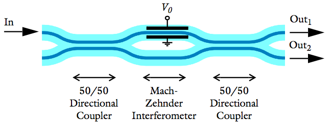
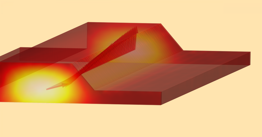
A Mach-Zehnder modulator with an applied voltage on one of the interferometer arms.
Designing a Mach-Zehnder Modulator
Suppose we want to design a Mach-Zehnder modulator. We need it to produce low loss, give us a 50/50 split of power through the two output arms, and be used as a spatial switch.
To determine the ideal design of the device, we turn to COMSOL Multiphysics and the Wave Optics Module.
Low Loss
In order to meet the general requirement of keeping the overall size of the device small, we need to find the smallest possible bend radius that also provides low loss. To figure this out, we can plot the total modal transmission over the increasing bend radius of the curvature. Doing so shows us that a minimum bend radius of 2.5 millimeters gives us an acceptable 2% loss (the plot depicts a total modal transmission of 98%). We can also confirm our results by generating an electric field norm plot.
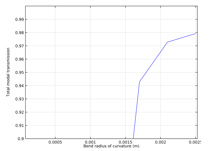
Plotting the total modal transmission over the bend radius of curvature in meters.
50/50 Split
Next, we have to find how long the coupler needs to be in order to give us our desired 50/50 split of incident power through the two output arms of the Mach-Zehnder interferometer. This can be achieved by monitoring the power difference in the two arms and sweeping the length of the coupler. If we plot the results of the parameter sweep, we will see that a coupler length of 380 μm will ensure a 50/50 split of power between the arms. Again, we can confirm our results with an electric field norm plot.
Here’s what the plot will look like:
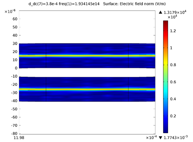
Electric field norm plot confirming that the power is close to equal in the two interferometer waveguide arms for a 380 micrometer long directional coupler. Gemetry is scaled by a factor of 80 in the y-direction.
Spatial Switch
Finally, we want to confirm that we can use the device as a spatial switch if we have a scenario where all the input and output ports are connected to other fibers or waveguides. In other words, we need to check that the wave can be switched between two output ports by applying a voltage across the waveguide in one of the arms and then tuning it. The below plot shows that we can, indeed, switch the output port by tuning the voltage:
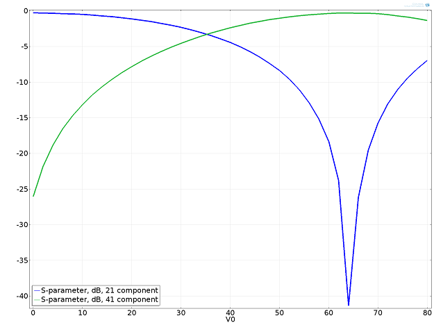
Transmission (y-axis) to the upper (blue line) and lower (green line) output waveguides versus the applied voltage (x-axis).
Note that if only one input and one output port are active, the device will act as an amplitude modulator instead of a spatial switch.
Model Download
- Learn how to run these simulations yourself, using COMSOL Multiphysics and the Wave Optics Module, by following the instructions in the Mach-Zehnder Modulator model example.

Comments (1)
Aly Abdou
August 25, 2022Is it possible to simulate MZI with MMI instead of the directional couplers in COMSOL?