Building Geometry Using COMSOL Multiphysics®
This course offers an introduction to building geometry in the COMSOL Multiphysics® simulation software. We will highlight various features that enable you to create the geometry your simulation requires. Each part of the course offers exercise files so that you can follow along with the processes described here and learn step-by-step how to create geometries from scratch.
The cross section for the chamber in a muffler being extruded to 3D (shown in Part 2 of this course).
Throughout the course we discuss the fundamental workflow for creating a geometry for your model, as well as best modeling practices. You may notice that the course primarily deals with creating geometry in the 2D or 3D spatial dimension, but the practices discussed are also applicable for creating 1D, 1D axisymmetric, and 2D axisymmetric geometries.
Part 1: Building 2D Geometry
- Sketch 2D geometry
- Use the software's built-in primitive objects to draw 2D geometry for commonly used shapes
Part 2: How to Expand 2D Designs to 3D Geometry
- Operations for expanding 2D geometry into 3D
Part 3: How to Use 3D Geometric Primitives and Operations to Build 3D Geometry
- Use the software's built-in primitive objects to generate 3D geometry for commonly used shapes
Part 4: How to Partition and Split Geometry into Separate Parts
- Split geometry into separate parts
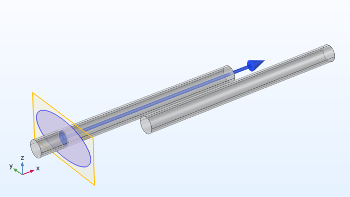
Part 5: How to Create 2D Geometry from Cross Sections of 3D Designs
- Convert 3D geometry into 2D
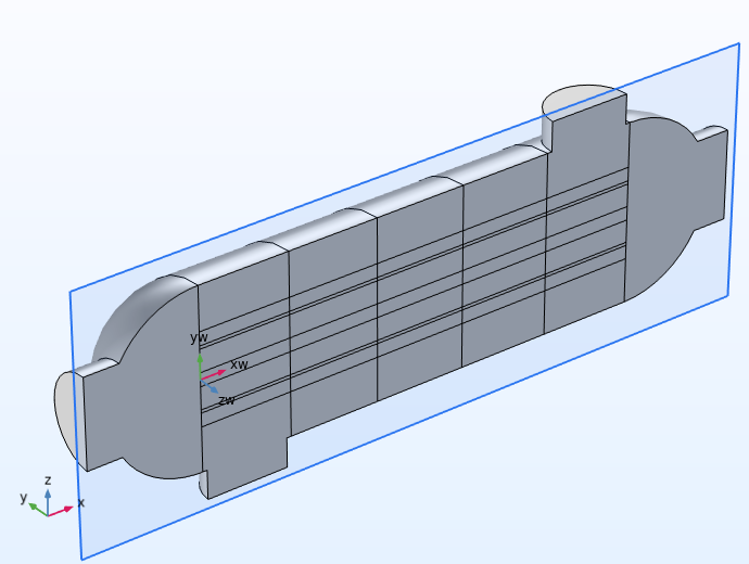
A 2D model of a shell-and-tube heat exchanger is obtained using a cross section of the 3D design (shown in Part 5 of this course).
After completing this course, we recommend watching our tutorial video Form Union and Form Assembly Geometry Finalization Methods, which explains how the final node in the geometry sequence, the Form Union/Form Assembly node, affects your geometry. It also covers how using the form union and form assembly methods affects the other steps in the modeling workflow, such as meshing the geometry or defining the physics.
Submit feedback about this page or contact support here.