How to Expand 2D Designs to 3D Geometry
When creating the geometry for a 3D model, it can be more efficient to first sketch the geometry cross section in 2D and then expand it to 3D. In this article, we will discuss the use cases and advantages of this approach and demonstrate how to do so.
Use Cases and Functionality
To obtain the final 3D geometry, sketching the geometry in 2D before expanding it to 3D is particularly useful when working with geometry that exhibits a type of symmetry, such as being symmetric along an axis or rotationally symmetric. It is also useful in general for building the geometry for 3D models since it can make the process more efficient.
 The resonator chamber of an automotive muffler model.
 The cross section of the automotive muffler's resonator chamber cross section.
The cross section (left) for the resonator chamber of an automotive muffler is extruded to a 3D object (right). The elliptical cross section was first sketched on a work plane in the xy-plane. Such a process was the most efficient way to generate the geometry for this part of the muffler.
 The cross section of a pacemaker electrode model.
 The cross section of the pacemaker electrode model in 3D.
The cross section (left) for part of a pacemaker electrode is revolved into a 3D object (right).
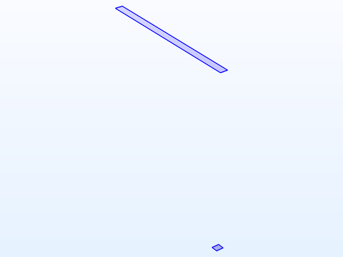
 The cross section of the carbon fiber model in 2D.
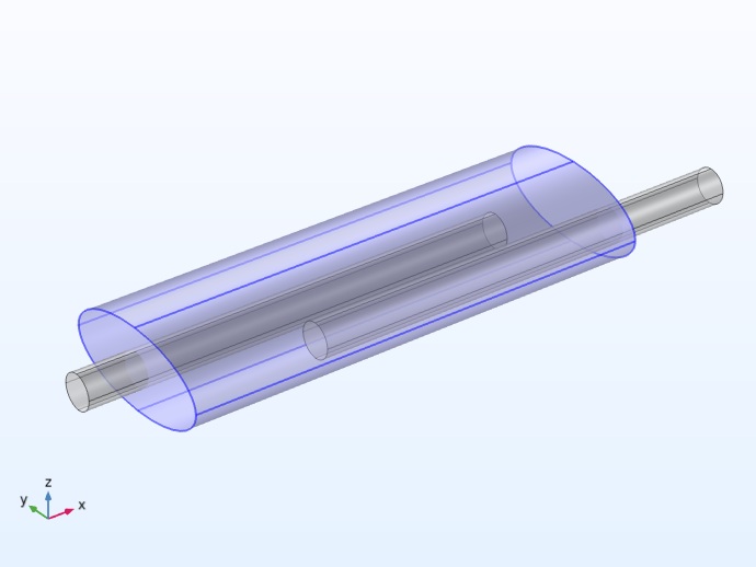
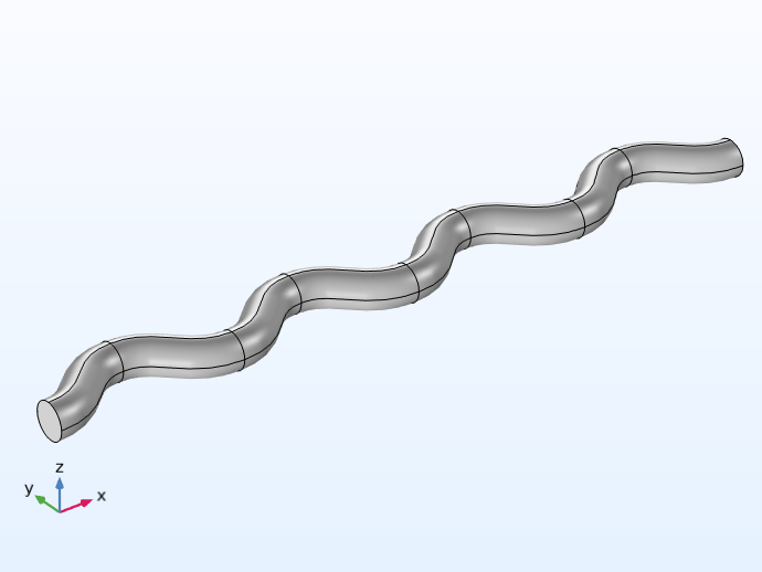 The carbon fiber model in 3D.
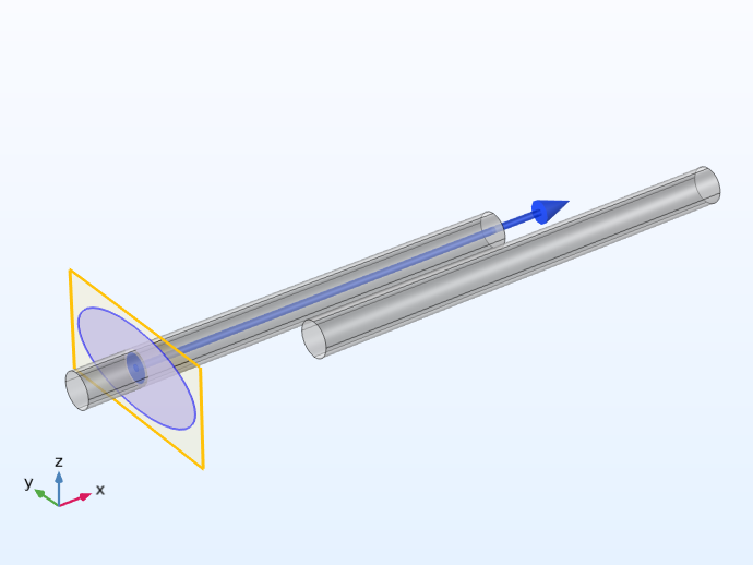
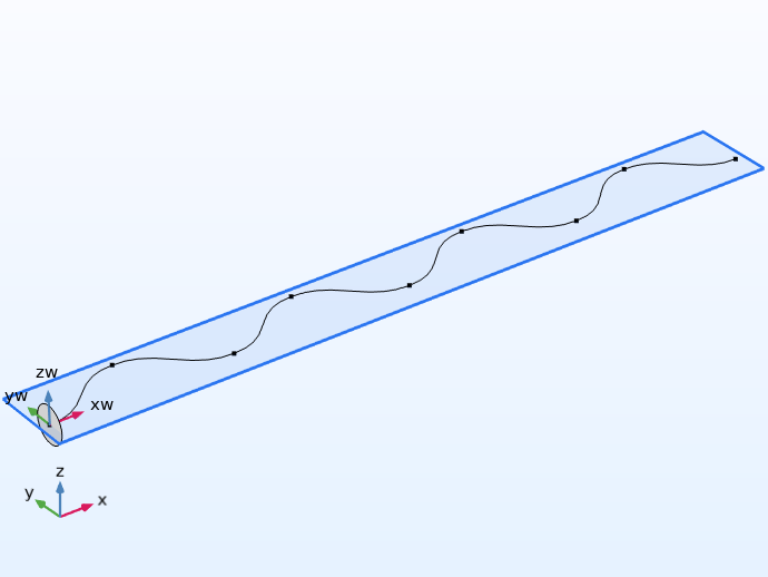
The cross section (left) for a carbon fiber is swept into a 3D object (right). The circular cross section was sketched on a work plane in the yz-plane, while the sweep path was drawn in the xy-plane.
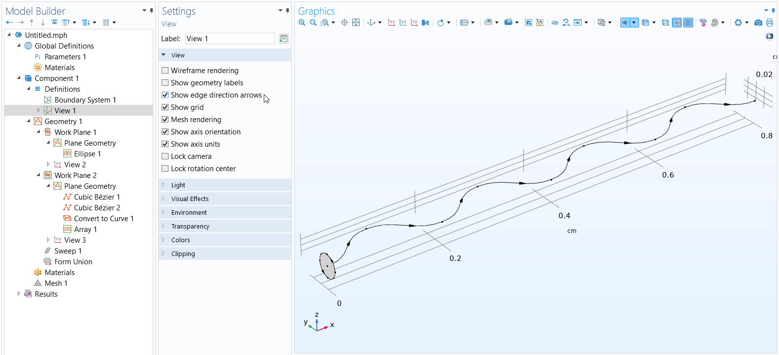 The COMSOL Multiphysics UI showing the Model Builder with the View node selected, the corresponding Settings window, and the Graphics window.
Before using the Sweep operation, you can confirm the sweep direction by going under the View node and selecting Show edge direction arrows. To see the arrows, make sure the Select Edges option is toggled on in the Graphics window toolbar.
Demonstration of the Sweep operation used to sweep an ellipse along a path in the xy -plane.
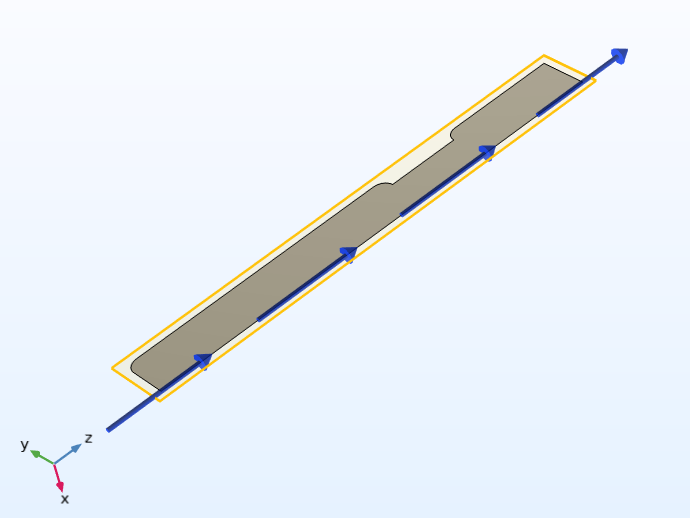
 Part of the 2D biconical frame antenna geometry.
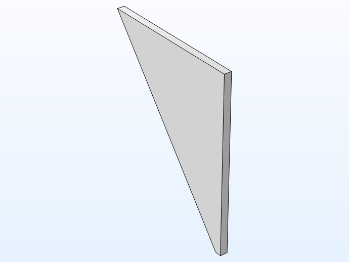 Part of the 3D biconical frame antenna geometry.
The 2D profiles (left) for part of the geometry of a biconical frame antenna are lofted into a 3D solid (right). Please note that this functionality requires the Design Module.
Demonstration of the Loft operation, used to loft a series of 2D profiles into a 3D solid.
COMSOL Multiphysics contains tools that enable you to easily create these types of geometries. In the software, you can expand many types of planar geometric objects into 3D by using work planes along with work plane operations, including:
- The Extrude operation, which is used to extrude planar objects to 3D and is useful when the cross section is symmetric along an axis
- The Revolve operation, which is used to revolve planar objects into 3D and is useful when the cross section is rotationally symmetric
- The Sweep operation, which is used to sweep surfaces along a spine curve and is useful when the cross section remains the same along a path
- The Loft operation, which is used to create a lofted 3D object from a set of 2D profiles (this functionality is not part of the COMSOL Multiphysics base package but is available with the Design Module)
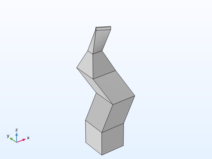 An abstract geometry resembling a column of block-like shapes that are, for example, displaced at different distances from a work plane and extruded to different lengths.
An example of a more complex extruded object. Model file attached here.
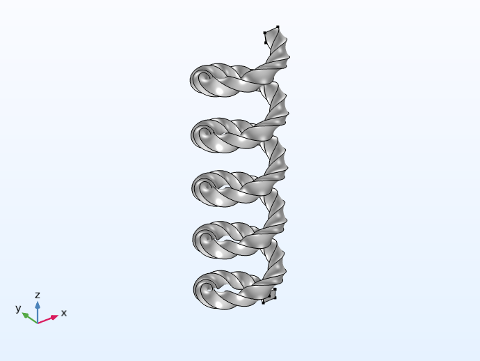 A helix-like geometry created using a sweep operation, with a twisted cross section along the length of the sweep path.
An example of a more complex geometry generated using a sweep path. Model file attached here.
Process for Expanding 2D to 3D
In COMSOL Multiphysics, expanding a 2D sketch to a 3D geometric object is done in three steps:
- Add the work plane in the 3D space
- Sketch the geometry in the work plane
- Expand the planar geometry to 3D
Watch the video below and follow along step-by-step in the software using the "start" reference files attached. We also discuss the process listed above in more detail.
Tutorial Video: How to Expand 2D Geometry to 3D
Modeling Exercises
Demonstrate the knowledge you have gained from this article by putting it into practice with the following modeling exercises. The directions provided are intentionally generalized to encourage self-guided problem solving. You can manually check your implementation with the solution model files provided here or use the comparison tool to identify the differences.
The 2D cross-sectional geometry for a shaft, part of a steam reformer, and tuning fork have been provided as downloadable MPHBIN files in this article. These MPHBIN files can be imported into COMSOL Multiphysics using the Import button in the Home ribbon tab or Geometry tab, as well as by right-clicking the Geometry node and selecting Import.
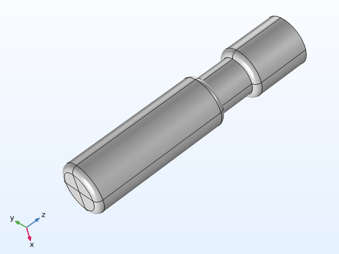
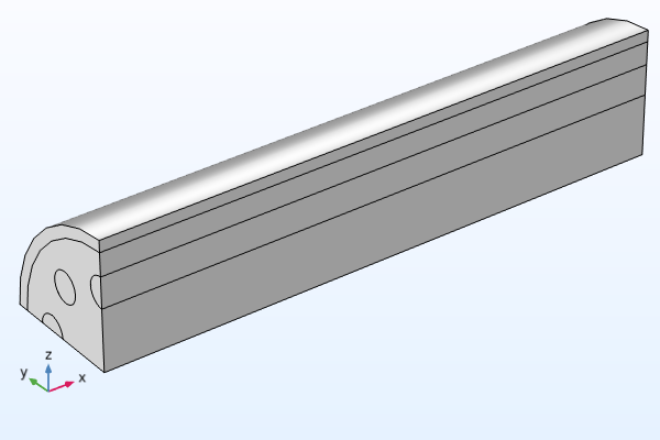
For each geometry, expand it to obtain the 3D design pictured below. Note that the shaft contains a hole (with a diameter of 4 mm) along the center, and the length of the steam reformer extends by 15 cm. You can measure the geometry to create a design with the same dimensions.
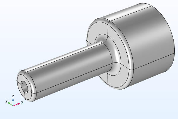 A 3D shaft model.
 A quarter of a 3D steam reformer model.
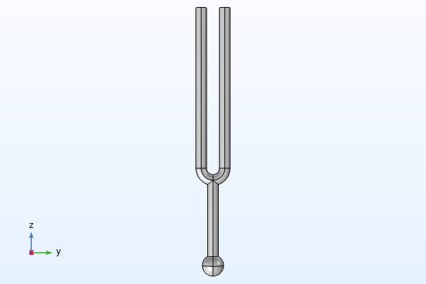 A 3D tuning fork model.
The model geometry of a shaft (left), a quarter of a steam reformer (middle), and a tuning fork (right).
The solution, 3D model files for the shaft, steam reformer, and tuning fork are available here.
Further Learning
There are several tutorial models available in the Application Libraries that provide a great deal of practice in building 3D geometries by expanding 2D sketches. We encourage you to create the geometry for the tutorial models listed here by following the step-by-step instructions in the documentation:
- Electrical Heating in a Busbar (extruding geometry)
- Piezoelectric Tonpilz Transducer (revolving geometry)
- Submarine Cable — Geometry & Mesh 3D in the Cable Tutorial Series (sweeping geometry)
To see additional examples of implementation, you can enter the following syntax in the search bar of the Application Libraries:
@geom:ext(extrude)@geom:rev(revolve)@geom:swe(sweep)@geom:loft(loft)
Submit feedback about this page or contact support here.