

Around this time last year, we introduced a new ribbon user interface to COMSOL Multiphysics. Now, with version 5.0, we are introducing many improvements that make COMSOL Multiphysics more intuitive to use. Updates include a change in color scheme, additional multiphysics interfaces, a materials tab, global materials, and Material Sweeps and Function Sweeps.
General User Interface (UI) Improvements
The overall color scheme has changed to structure and organize the information better, as well as to reinforce the COMSOL Multiphysics workflow. Each workflow step has its own color. For example, all the Geometry icons are red-orange, all the Materials icons are yellow-orange, all the Physics icons are blue, and all the Results icons are red. The Results tab also has different icons for the various dimensions:
3D: ![]() , 2D:
, 2D: ![]() , 1D:
, 1D: ![]() .
.
")
The new color scheme helps to differentiate between the model workflow steps.
Multiphysics Interfaces
Last year’s introduction of the Multiphysics node really spoke to our product and who we are as a company. Setting up models with multiple physical phenomena should be as easy as it is with one phenomenon. The Multiphysics node helps realize that notion; you model one physics at a time and the multiphysics nodes automatically couple the different physics together.
With COMSOL Multiphysics 5.0 , we are introducing an additional 15 multiphysics couplings to the Multiphysics node, spanning several application areas (required modules are listed in parentheses):
- Non-Isothermal Flow including Conjugate Heat Transfer (CFD Module or Heat Transfer Module)
- Fluid-Structure Interaction for Fixed Geometry (Structural Mechanics Module or MEMS Module)
- Semiconductor-Electromagnetic Waves Coupling for Optoelectronics (Wave Optics Module and Semiconductor Module)
- Plasma Heat Source (Plasma Module)
- Lorentz Force (Plasma Module)
- Static Current Density Component (Plasma Module)
- Induction Current Density Component (Plasma Module)
- Piezoelectric Effect (Structural Mechanics Module, MEMS Module, or Acoustics Module)
- Acoustic-Structure Boundary (Acoustics Module)
- Thermoacoustic-Structure Boundary (Acoustics Module)
- Aeroacoustic-Structure Boundary (Acoustics Module)
- Acoustic-Porous Boundary for Poroelastic Waves (Acoustics Module)
- Porous-Structure Boundary for Poroelastic Waves (Acoustics Module)
- Background Potential Flow Coupling (Acoustics Module)
- Acoustic-Thermoacoustic Boundary (Acoustics Module)
Emphasis on Materials
A few of the more significant UI-related improvements involve materials. The ribbon now contains a Materials tab to go along with the other steps in the workflow, and materials can now be created globally for models with the same materials in multiple components. This lends itself to the most significant new addition, which is the new “Switch” feature to power material sweeps and function sweeps.
With the new material sweep feature, you use the available materials with their defined material properties directly in a sweep, avoiding the tedious task of re-entering material properties or material property functions. Previously, you had to manually enter material property values, which was rather time consuming. Alternatively, if your material properties could only be defined as functions and you wanted to sweep over properties described by different functions, you had to get clever in setting up a parameter sweep. The parameters were abstract values included to control which parts of the function would be active for a particular step in the sweep. This made it difficult to postprocess the results and opened up the possibility for errors.
Now, the definition of a material sweep is much easier to define and it is also easier and more intuitive to process the results as you get the actual material names and values in the plot settings along with derived value evaluations. Functions are generic in COMSOL Multiphysics. Therefore, the function sweep is introduced, in analogy to the material sweeps, to define domain settings, boundary conditions, initial conditions, loads, constraints, etc.
First, you must create a Switch under one of the Materials nodes. If you don’t have materials already, create them from the Switch node. Otherwise, simply drag and drop previously defined materials in the model tree into the Switch node. In the Study tab, there is a “Material Sweep” button. After adding the Material Sweep, you will be prompted to add a Switch function and choose which cases in the Switch should be included. After running the simulation, you can switch between the materials that were swept over and examine the varying results. A “Function Sweep” works the same way. As I mentioned earlier, the Switch function can be applied globally or locally.
")
A view of the Model Builder window with an added Switch, with two materials and Material Sweep.
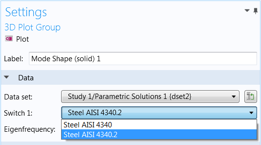
The results settings, switching between the two materials.
Further Reading
All of these details and more can be found on our Release Highlights page (including videos!)


Comments (0)