

Impressed current cathodic protection is a common method for protecting metallic structures against galvanic corrosion. In this blog post, we explain how the method works and for which applications it is commonly used. An example of such simulations on a ship hull is shown, and the key points for implementation are explained. In this model, one of the important aspects is the electric field signature that results from the cathodic protection system of the shaft and propeller onboard.
Protecting Against Galvanic Corrosion
By putting a metal into an electrolyte, you will always have the risk of galvanic corrosion. This will occur in water environments, soils, concrete, and even at atmospheric conditions where only a thin film of electrolyte will form as moist air condenses on the surface. Wherever you have a medium that is surrounding the metal and is capable of transporting ions from one site of the metal to another site, you will have corrosion. Even a metal that is seemingly of the same type, such as cast iron, will corrode by itself just because of impurities in the metal or different phases of the metal itself that can have a different electrochemical potential than other parts of the structure.
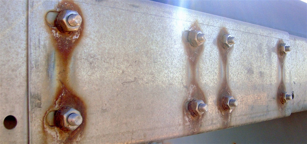
Galvanic corrosion of bolts on a plate. Image by D3j4vu — Own work. Licensed under CC BY-SA 3.0, via Wikimedia Commons.
Galvanic corrosion will lead to problems such as pitting corrosion and crevice corrosion if the structure is not protected. In order to mitigate such problems, you may want to isolate the structure from the electrolyte environment by painting it with a polymer coating. However, such coatings may be destroyed by impact or something penetrating the barrier over time and lead to corrosion.
In many cases, you would typically have another mechanism to avoid galvanic corrosion if your first barrier is destroyed. This can be achieved by polarizing the structure so that it becomes the cathode of the system. Then, the cathodic reactions will govern the exposed material, and the material loss due to anodic reactions will be negligible. There are two common methods of doing this:
- Sacrificial anode cathodic protection (SACP)
- Uses a sacrificial metal with a lower electrochemical equilibrium potential
- Impressed current cathodic protection (ICCP)
- Uses an external current source, usually a rectifier, which creates a DC current that polarizes the surface of the metal into a cathodic potential region
- The current source is connected to some anodes that are made from an inert material, and thus are not consumed, as with sacrificial anodes
The ICCP method is commonly used for onshore pipelines, in harbors, in concrete structures, and on ships and other structures where it is feasible to use. It is also a popular method for retrofitting corrosion protection systems in offshore oil platforms due to the high current output and ease of installation.
One major drawback with ICCP is that the current output may be large, yielding very negative polarization of the metal surfaces nearby. This can polarize the cathode into a region where hydrogen evolution occurs. For certain structures, hydrogen will diffuse into the metal surfaces and create a risk for hydrogen embrittlement and hydrogen-induced stress cracking (HISC) in the metals.
SACP may be used for steel structures more often, because the risk of hydrogen evolution is less prominent. On large marine vessels, it is a very common method for cathodic protection. The anodes used for the impressed current can be embedded in the hull surface of the vessel, and thus create a very low drag resistance compared to a sacrificial anode with the same current capacity.
Modeling Impressed Current Cathodic Protection
Modeling corrosion can be a truly challenging project if you want to capture all of the details of the physics and electrochemistry in the context of a geometrically large structure. Luckily, when modeling cathodic protection on larger scales, such as ship hulls, pipelines, or oil platforms, you can make some assumptions and valid simplifications.
By starting out with the governing equations and the assumption of a well-mixed electrolyte, you can simplify the equation so that you only calculate the current balance in the electrolyte caused by charge migration. This reduces the governing equation to the Laplace equation, where the conductivity of the electrolyte enters as a material parameter.
The equation for the current density balance is given by
where
Here, i_l defines the current density in the electrolyte, n is the number of species, z is the charge of the ion, u_{m,i} is the mobility of the ion, F is the Faraday’s constant, c is the species concentration, \phi_l is the electrolyte potential, and \mathbf{u} is the velocity vector that describes the flow of the electrolyte.
The second term on the right-hand side of the equation above contains the electroneutrality condition as a factor, which is equal to zero. The factor within parentheses in the first term on the right-hand side of the equation above is equal to the electrolyte conductivity, \kappa_l. This yields the following expression for the current density in perfectly mixed electrolytes:
On all metallic surfaces, you can have both anodic and cathodic reactions going on. These reactions can be represented by current densities determined by the Butler–Volmer or Tafel equations that are often used. The Butler–Volmer equation gives the rate of an electrochemical reaction as a function of the electrochemical potential at the surface site. Using Faraday’s law, this gives the current density, since electrons are involved (Ref. 1). The Butler–Volmer equation may describe, for example, the hydrogen evolution reaction that occurs on the cathode:
where i_{0,H_2} is the exchange current density, c_{OH^-} is the dimensionless hydroxide ion concentration, P_{H_2} is the dimensionless hydrogen partial pressure, R is the universal gas constant, T is the temperature, and \eta is the activation overpotential.
The activation overpotential is defined as:
\eta= \phi_s-\phi_l-E_{eq},
where \phi_s denotes the electric potential at the surface and E_{eq} denotes the equilibrium electrode potential measured toward a specific reference electrode common to all reactions in your system.
By giving the different parameters in these equations, you can get polarization curves such as in the figure below:
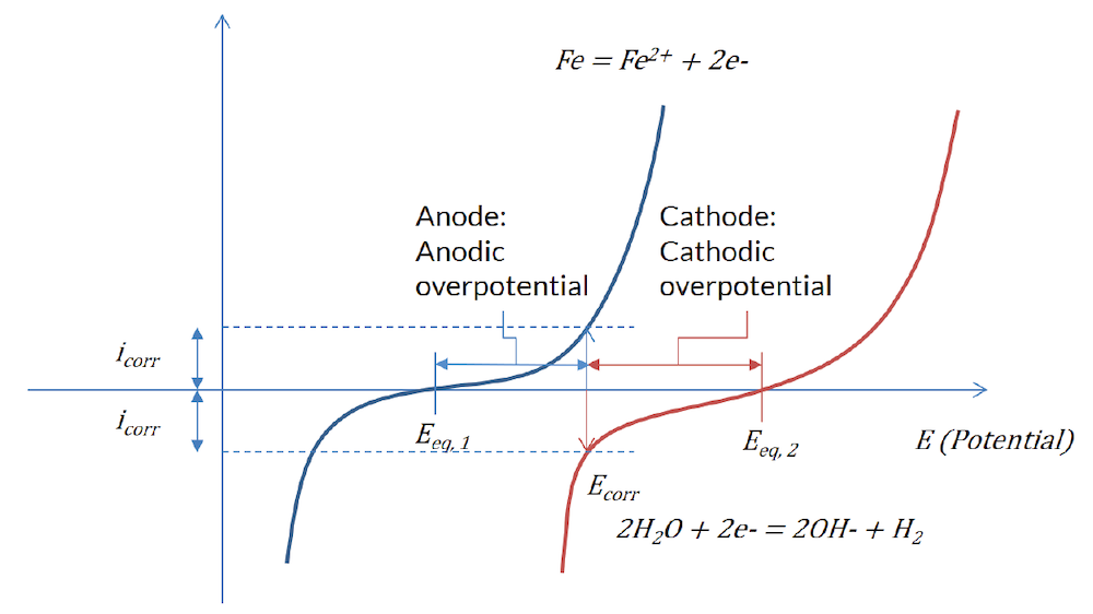
Figure 1: The Butler–Volmer expression for the reaction at the less noble metal surface (blue) and the more noble metal surface (red).
These polarization curves are also commonly displayed as an Evans diagram:
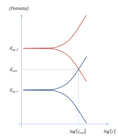
Figure 2: Evans diagram for two electrode reactions in the absence of ohmic and mass transport losses.
For the impressed current anode, you typically set the current density so that the system achieves a given electrolyte potential at a reference electrode. This constitutes the material parameters and boundary conditions needed to simulate cathodic protection with impressed currents.
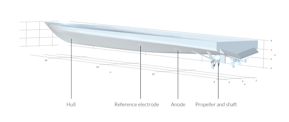
Figure 3: Schematic view of the ship hull with the positions of reference electrode, anode, propeller, and shaft.
Setting Up a Model of ICCP on a Ship Hull
In the given example, which also can be found in the Application Gallery, we study a ship hull with a shaft and propeller that is protected by impressed currents. The difference between coated and uncoated propellers is also studied. The goal is to evaluate the potential profile along the keel of the boat for the two different cases. This is important in naval military applications where you want to know the magnitude of your electric and magnetic signature in seawater.
Once the geometry is imported and you have defined the electrolyte domain, there are a few key steps for this type of simulation:
- Define the reference electrode (Figure 4)
- Add an Electrolyte Potential boundary condition set to, e.g., 0 V at the geometrically stable impressed current anode
- Refer to the reference electrode in the settings for the exposed metal surface, and set the Electrode potential vs. reference to the desired protection potential difference at the reference electrode (Figure 5)
- Input the corresponding equilibrium potentials and reaction parameters for your respective metals that are exposed to the electrolyte (Figure 6)

Figure 4: Settings from the Reference Electrode in a point.

Figure 5: Settings for the electrode surface of the metal that you intend to protect with impressed currents.

Figure 6: Settings for the electrode reaction on the protected metal of the shaft in the model.
Results and Discussion
The electrode potential vs. reference electrode is the most common quantity to evaluate when working with marine corrosion. By looking at the different potentials, you will get a clear indication of whether the objects are protected, and if you have regions where, for example, hydrogen evolution can occur and a better electric shielding should be applied. Below, you can see the potential on the surface of the ship hull.
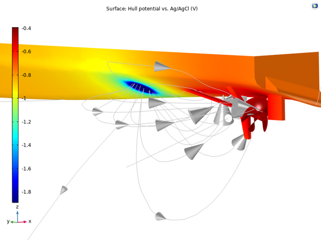
Figure 7: Electrode potential vs. Ag/AgCl reference electrode for the ship hull with impressed cathodic current protection for a nickel aluminum bronze (NAB) shaft with an Alloy 625 propeller.
By investigating the electrode potential vs. Ag/AgCl along the keel of the ship hull in this model, you will get an indication of how much the electric field signature is affected by the use of a coated or uncoated propeller. You can clearly see that the coated propeller gives a lower variation in electrolyte potential, and thus will give a lower electric field signature around the ship.
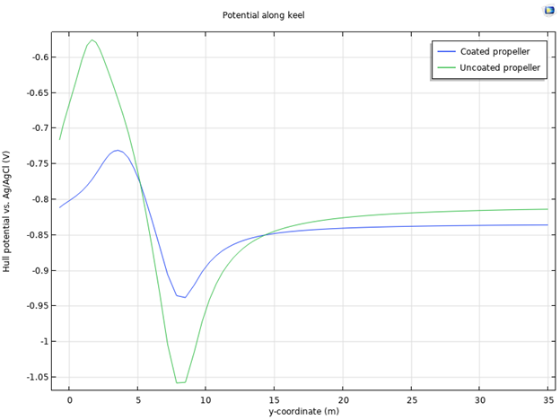
Figure 8: Comparison of the electrode potential vs. Ag/AgCl reference along the keel of the hull with coated and uncoated propeller, respectively.
Next Steps
Learn more about the Corrosion Module and how it can fit your corrosion protection analysis needs.
Further Resources
- Read this white paper on corrosion and corrosion protection
- Try modeling the impressed current protection of a ship hull
- Check out the corrosion models in the Application Gallery
Reference
J.O. Bockris and A.K.N. Reddy, ”Modern Electrochemistry”, vol. 2, pp. 862–908, Plenum Press, 1970.


Comments (0)