

Reciprocating engines are used extensively for power generation in a variety of applications, most notably within the automobile industry. In the design process, it is important to ensure that all of the engine’s parts can withstand high stresses and loads in order to maximize the operational lifetime. Here, we analyze fatigue in an engine’s connecting rods.
Turning Pressure into Rotating Motion
Many of today’s motor vehicles rely on reciprocating piston engines as their source of power. In an internal combustion reciprocating engine, fuel combines with an oxidizer in a combustion chamber. The combustion causes the gases to expand, applying pressure to the engine’s piston, pushing it out of the chamber. The linear movement of the piston is converted to a rotating motion by way of a connecting rod, which joins the piston to the crankshaft. This continual motion exerts a great deal of stress on the connecting rod — a force that becomes greater with increasing engine speeds.
Within reciprocating engines, it is crucial that each component is analyzed critically, since one part’s failure often means replacing the entire engine. To optimize the design of this engine and ensure a long operational lifetime, we can analyze the connecting rods from the fatigue viewpoint.
Stress and Fatigue in a Reciprocating Engine
The High-Cycle Fatigue of a Reciprocating Piston Engine model is based on an example of a three-cylinder reciprocating engine from the Multibody Dynamics Module. In this engine, a flywheel is mounted on the crankshaft, with the assembly supported on both ends by journal bearings. The model also features three sets of cylinders, pistons, and connecting rods that are identical. Hinge joints are used to connect the bottom ends of the connecting rods to the common crankshaft as well as to connect the pistons to the top ends of the rods. A prismatic joint is used to connect each of the cylinders to a piston.
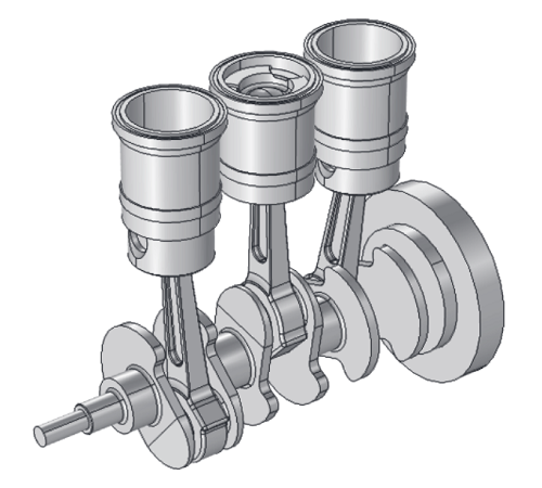
Reciprocating engine geometry.
Aside from the flexible central connecting rod, it is assumed that the engine components are rigid. The cylinders are fixed and the other parts of the engine are able to freely move in space. The engine as a whole operates at 1,000 RPM and the material data is derived from structural steel, which shows a fatigue limit at 210 MPa.
Our analysis begins with the stress history in the connecting rod fillet, as a stress concentration resulting from geometrical change is assumed in this area. After a few revolutions, the engine reaches a steady-state behavior. Following the third cycle, the stress history seemingly repeats itself for each cycle, as shown in the plot below. The third principal stress dominates the connecting rod’s stress history as the part is in compression during this time. Because the first and second principal stresses are small compared to the third one, we can consider the stress state at the fillet to be uniaxial. Since the von Mises stress would be better suited in a multiaxial loading, we use the principal stress as the amplitude stress in the Basquin relation.
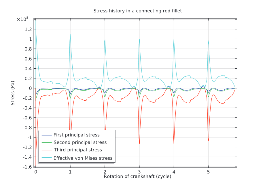
The stress history in a connecting rod fillet.
The following plot addresses fatigue life prediction in the connecting rod. Here, the point of focus is the fillet near the top end of the rod. According to the Basquin model, the fatigue life is predicted to be more than twenty-five billion cycles, which is a notably long operational lifetime. Although the endurance limit is not defined in the Basquin model, the relation can be used to back-calculate the fatigue life at the endurance stress to 245 million cycles. Since the model prediction gives a greater life than the back-calculated fatigue life at the endurance limit, we can assume then that the stress within the engine’s assembly is beneath the endurance limit, which as previously noted is 210 MPa for the used material, and that the connecting rod has an infinite operational life.
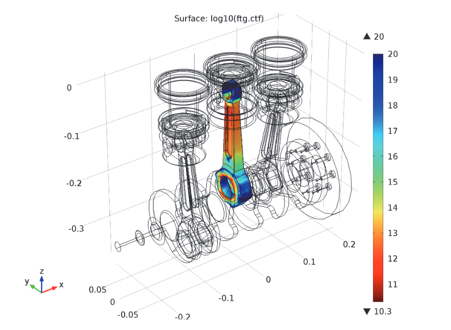
The connecting rod’s fatigue life prediction.
The initial stress history plot also indicates that the rod is designed for infinite life. With a principal stress range around 110 MPa, the stress amplitude is near 55 MPa, which is lower than the material’s endurance limit.
Try It Yourself
- Download the model: High-cycle fatigue of a reciprocating engine


Comments (0)