

Thin dielectric films are versatile tools for controlling the propagation of light. They can be used, for example, as anti-reflective coatings to reduce the amount of stray light in a system. They can also be used as low-loss reflectors or as filters to selectively transmit certain frequencies of radiation. Here, we’ll discuss some of the built-in tools that the Ray Optics Module provides for modeling optical systems with dielectric films.
Understanding Thin Films and Transmittance
Because the optics of thin dielectric films is based on reflection and refraction at multiple surfaces, we begin by reviewing the governing equations for reflection and refraction at a single boundary between two media, called a material discontinuity. The reflection and refraction of light at the boundary is governed by the Fresnel equations:
(1)
t_s &= \frac{2n_1 \cos\theta_i}{n_1 \cos\theta_i+n_2 \cos\theta_t} \\
t_p &= \frac{2n_1 \cos\theta_i}{n_2 \cos\theta_i+n_1 \cos\theta_t} \\
r_s &= \frac{n_1 \cos\theta_i-n_2 \cos\theta_t}{n_1 \cos\theta_i+n_2 \cos\theta_t} \\
r_p &= \frac{n_2 \cos\theta_i-n_1 \cos\theta_t}{n_2 \cos\theta_i+n_1 \cos\theta_t}
\end{aligned}
where n_1 and n_2 are the refractive indices in the adjacent domains containing the incident and refracted rays, respectively, \theta_i is the angle of incidence, and \theta_t is the angle of refraction. This is illustrated by the following diagram.
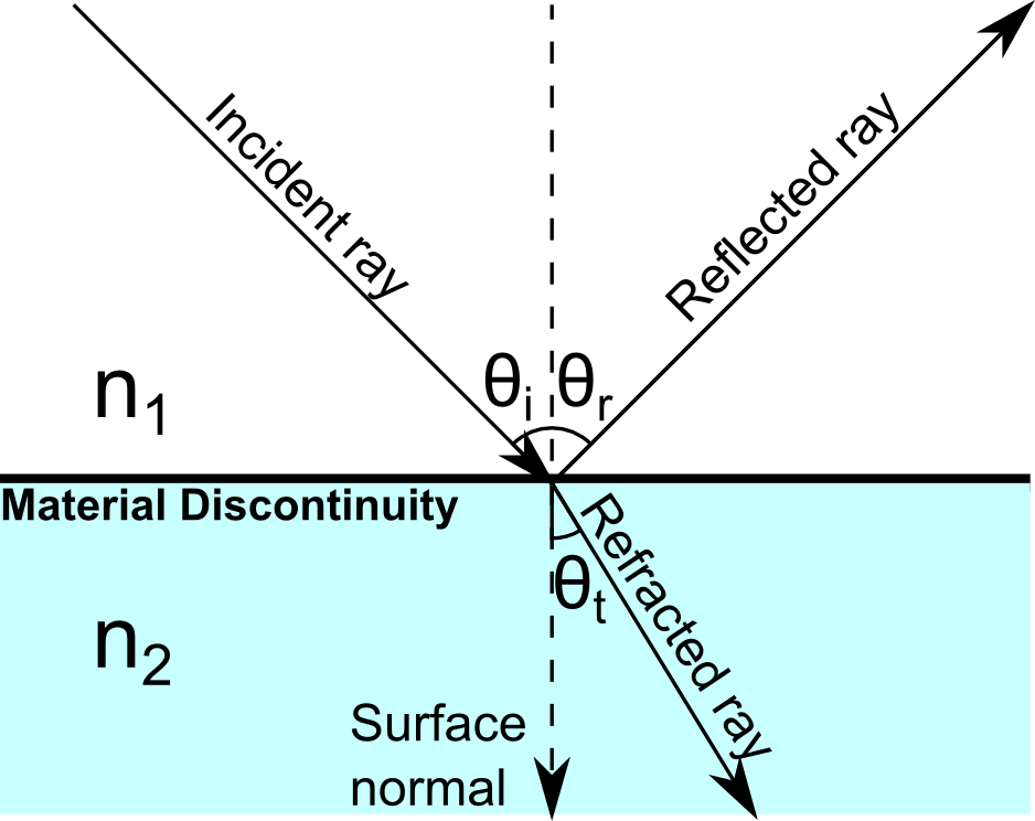
The coefficients r and t are the reflection and transmission coefficients, respectively. The subscripts s and p indicate the polarization of the incident ray. If the electric field vector is normal to the plane of incidence (the plane containing the incident ray and the surface normal), the ray is s-polarized; if the electric field vector lies in the plane of incidence, the ray is p-polarized.
For clarity, in the following discussion we drop the suffixes that indicate s- and p-polarization and assume that the correct reflection and transmission coefficients are used.
If the incident ray has intensity I_0, the reflected and refracted rays have intensity given by
(2)
I_r &= R I_0 \\
I_t &= T I_0 \\
R &= \left|r\right|^2 \\
T &= \frac{n_2 \cos\theta_t}{n_1 \cos\theta_i}\left|t\right|^2
\end{aligned}
The quantities R and T are called the reflectance and transmittance, respectively. By combining Eq.(2) with either set of Fresnel coefficients from Eq.(1), we observe that energy is conserved, I_r+I_t=I_0.
We now consider what happens if rays are reflected and refracted at two parallel boundaries that are separated by a small distance. These two boundaries are the surfaces of a thin dielectric film that separates two media. By “small”, we usually mean that the film thickness is comparable in magnitude to the electromagnetic wavelength. Let us assume that the film thickness is much smaller than the coherence length of the radiation — in other words, over a length scale comparable to the film thickness, we can treat electromagnetic waves as perfect sinusoidal curves. We wish to compute the intensity of radiation that propagates into the domains on either side of the thin film.
As illustrated below, we can imagine a single ray entering a narrow region of refractive index n_2, sandwiched between media with indices n_1 and n_3. Let r_{12} indicate the reflection coefficient at the interface between domains 1 and 2, while r_{23} indicates the reflection coefficient at the boundary between domains 2 and 3.
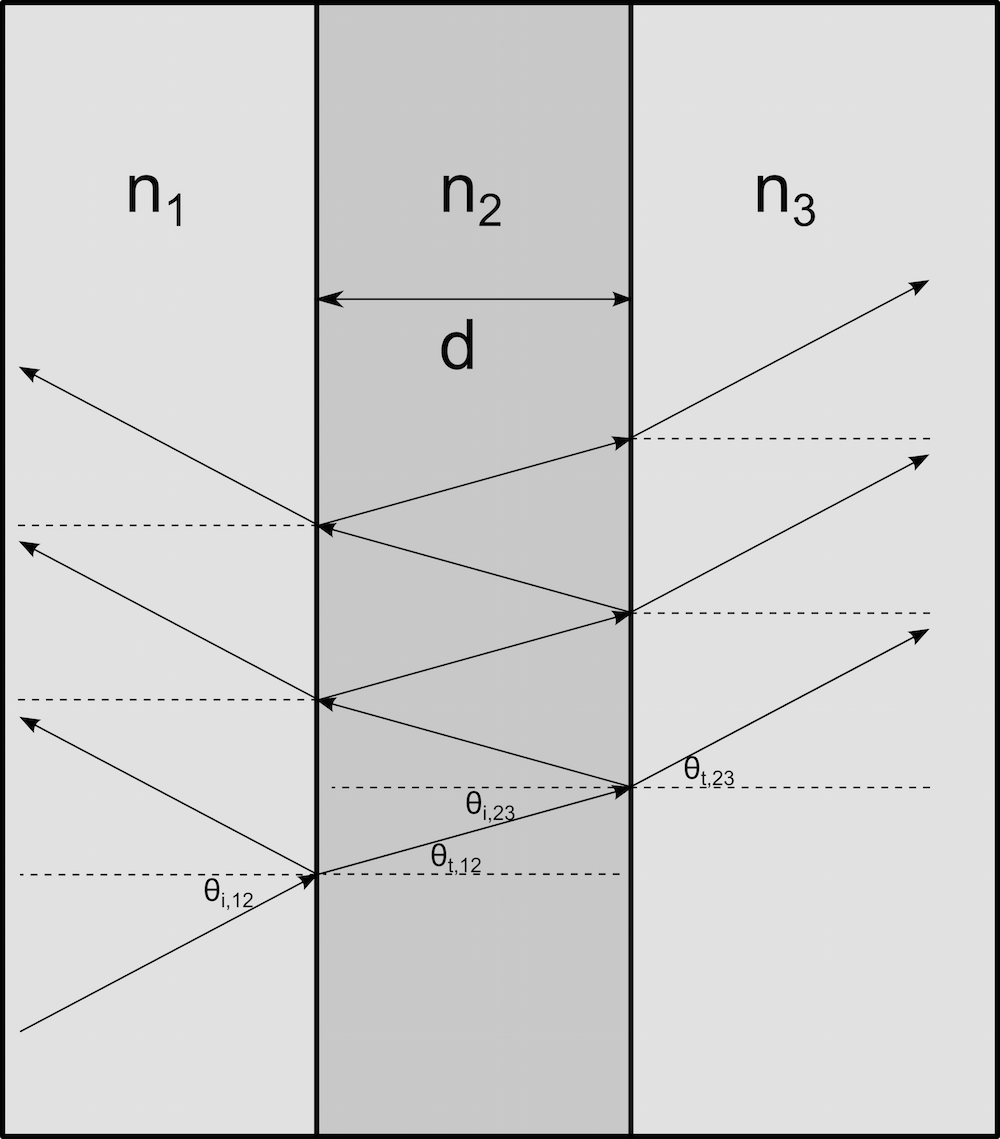
After entering the thin film, the ray is reflected back and forth between the two boundaries. Every time the ray reaches a boundary with a neighboring domain, a refracted ray propagates into that domain, causing the intensity within the film to be reduced. The amplitudes of the multiple rays that propagate into the domains adjacent to the film will all contribute to the total reflected and transmitted fields. Because each of these rays travels a different distance within the film, they may interfere constructively or destructively with each other — that is, the total amplitude of the transmitted and reflected fields can increase or decrease, depending on the phase difference between the rays.
Because of these interference effects, the intensity of the reflected and refracted radiation depends on the ratio of the free-space wavelength, \lambda_0, to the film thickness, d, not just on the medium properties and angle of incidence. As per Optical Properties of Thin Solid Films by O. S. Heavens (1991), the equivalent reflection coefficient req for the single-layer film is given as
(3)
where \delta is the phase delay that is introduced by crossing the film:
(4)
and \theta_2 is the acute angle that the ray makes with the surface normal as it propagates through the film. If multiple thin layers are placed side-by-side, it is possible to use Eq.(3) recursively to compute the transmittance and reflectance of the entire structure. There are also several other algorithms that can be used to compute the transmittance and reflectance of a multilayer film. See, for example, Optical Properties of Thin Solid Films by O. S. Heavens (1991) and Principles of Optics by M. Born and E. Wolf (1999).
Anti-Reflective Coatings
We have seen that, due to the interference of electromagnetic waves on either side of a thin film, the transmittance of the film can be significantly larger or smaller than the transmittance of a single boundary between two media, depending on the medium properties, film thickness, wavelength, and angle of incidence. We can use this behavior to control the amount of transmitted or reflected radiation in an optical system.
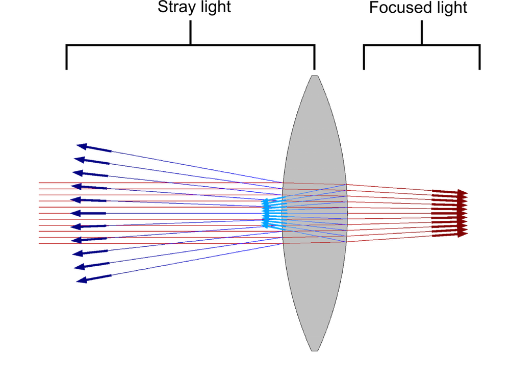
When thin dielectric films are used to reduce the reflectance at a material discontinuity, such films form an anti-reflective coating. The coating may consist of a single layer or multiple layers. Anti-reflective coatings can significantly reduce the amount of unwanted or unintended radiation, called stray light, in an optical system. For example, suppose that light propagating through a room is focused by a glass lens with a refractive index of 1.45. Assuming that the angle of incidence is nearly 0, the reflectance of the glass surface is
(5)
That is, more than 3% of the radiation is reflected immediately when reaching the lens, reducing the amount of light that can be properly focused by the lens. Usually, we wish to reduce the amount of stray light as much as possible.
For example, if the reflection coefficients on both sides of the film are equal, r_{12}=r_{23}, and the phase delay for rays crossing the layer is \delta = \pi/2, then, by applying Eq.(3) we find that r_{\textrm{eq}}=0 and no radiation is reflected at all. For rays at normal incidence, we can obtain the desired phase delay by adjusting the thickness of the layer so that d=\lambda_0/(4n_2), i.e., the optical thickness of the single-layer coating is a quarter of the wavelength. To ensure that r_{12}=r_{23}, the refractive index of the film should be the geometric mean of the refractive indices on either side, n_2=\sqrt{n_1 n_3}.
The single-layer coating we’ve just described would have a reflectance of exactly zero, but only for a specific frequency of radiation and a specific angle of incidence. In addition, we might not have access to a material with a refractive index equal to the geometric mean of the refractive indices on either side of the film. A solution to this dilemma is to use a multilayer film that is capable of providing consistently low reflectance across a wide frequency band while also providing more flexibility in the selection of materials.
The Ray Optics Module includes settings for applying single-layer or multilayer films to surfaces. It includes a built-in option to apply single-layer anti-reflective coatings at boundaries. There are also built-in settings for applying single-layer films that have a specified reflectance or transmittance for a certain refractive index, electromagnetic wavelength, and angle of incidence. Alternatively, single-layer or multilayer films can be applied at boundaries by specifying the refractive index and thickness of each layer directly.
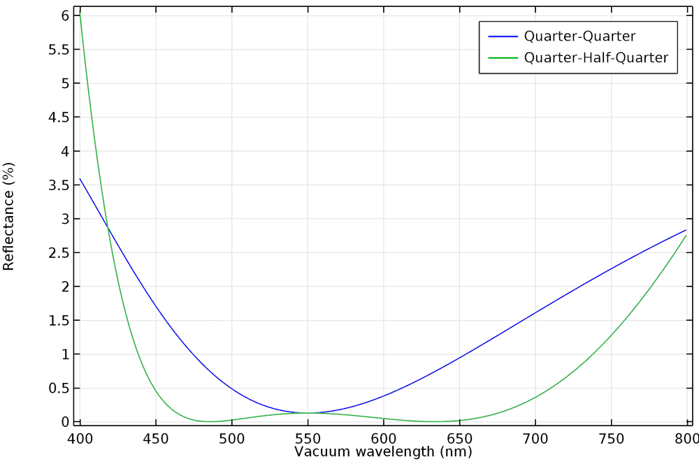
For example, the following plot compares the reflectance of an anti-reflective coating with two layers, each of which has a thickness equal to 1/4 of the wavelength, to an anti-reflective coating consisting of three layers with thicknesses of 1/4 of the wavelength, 1/2 of the wavelength, and 1/4 of the wavelength, respectively. We see that the quarter-quarter film provides a reflectance of less than 0.5% over a range of about 100 nm, whereas the quarter-half-quarter film provides a reflectance of less than 0.5% over a range of more than 250 nm.
For more information about the set-up of thin dielectric films, see the Anti-reflective Coating, Multilayer tutorial.
High-Reflection Coatings
Thin dielectric films can also be used to increase the reflectance at a boundary, creating mirrors with significantly lower losses than shiny metallic surfaces. These arrangements of films are called high-reflection coatings or distributed Bragg reflectors (DBRs). The DBR consists of alternating layers of higher refractive index n_H and lower refractive index n_L, as shown below.
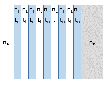
The thicknesses of the layers are determined by the equation
(6)
The DBR is characterized by a photonic stop-band \Delta \lambda_0, which is the range of wavelengths over which the reflectance is nearly 1:
(7)
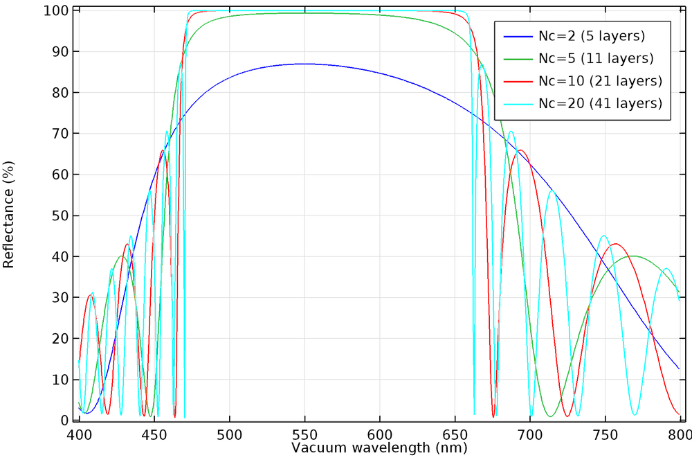
The reflectance becomes closer to 1 within the stop-band as the number of layers is increased.
To learn more about the set-up of distributed Bragg reflectors, see the Distributed Bragg Reflector tutorial.
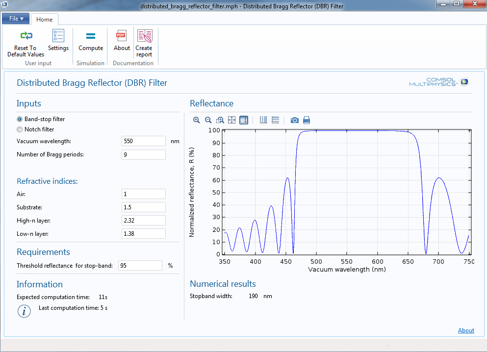
This tutorial is also available as a runnable application. With the Distributed Bragg Reflector (DBR) Filter application, you can compute the reflectance of a DBR over a wide frequency range. In addition to plotting the reflectance as a function of the vacuum wavelength, the application also computes the width of the stop-band, defined as the region in which the reflectance exceeds a specified threshold.
As we’ve seen previously, the optical thickness of each layer in a typical DBR is equal to \lambda_0/4. If a layer of optical thickness \lambda_0/2 is inserted within the DBR, then it becomes possible to transmit radiation of a specific frequency within the stop-band, as illustrated below.
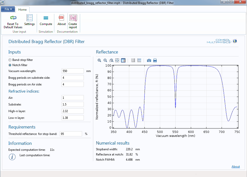
This type of filter is useful for transmitting radiation from a spectrally narrow source while rejecting contamination from other sources.
You can download the Distributed Bragg Reflector (DBR) Filter app here.
Learn More
- See what else is new in the Ray Optics Module with COMSOL Multiphysics version 5.1, released on April 15, 2015.


Comments (7)
Catherine O'Hearn
February 18, 2019Hello,
Is it possible to model a thin dielectric film with a frequency dependent permittivity tensor or refractive index?
Thank you
Christopher Boucher
February 19, 2019Hi Catherine,
Yes, it is possible to enter a frequency dependent refractive index for the thin dielectric film. To include the frequency or wavelength in the expression for the refractive index, you must use a special operator called ‘noenv’. So, for example, if you want the refractive index to be an analytic function of the vacuum wavelength gop.lambda0, then you might enter an expression like
an1(noenv(gop.lambda0))
where ‘an1’ is an analytic function defined elsewhere in the model.
This ‘noenv’ is a special way of telling the software that the variable gop.lambda0 is defined on the rays, not on the boundary. The same could be said for the frequency gop.nu or angular frequency gop.omega.
Catherine O'Hearn
February 19, 2019Christopher,
Thank you for your response! I am looking to model a hyperbolic material, so the thin dielectric film would also need to be anisotropic. is this possible? Or should I just model it in the Wave Optics module?
Catherine O'Hearn
February 19, 2019I’m trying to model the Fresnel reflection coefficient through a layered system, and I thought that the Ray Optics module computed these automatically, making it easier than trying to enter a formula for a layered system into Wave Optics. My other thought was to use the Ray Optics Module, but just call the hBN (the anisotropic thin layer) a layer in the geometry setup.
I’d appreciate any further help you can offer!
Christopher Boucher
February 20, 2019Hi Catherine,
At the time of writing (V5.4), the Ray Optics Module always treats the thin dielectric films as having isotropic refractive index. Eventually we’d like to support birefringence in a future version.
Henrik Parsamyan
November 24, 2022Hi Christopher,
Thank you for the super helpful article.
I am studying the interference theory and tried to repeat the results presented in the manuscript “Antireflection Coating Using Metamaterials and Identification of Its Mechanism” by Chen et al, DOI: 10.1103/PhysRevLett.105.073901 (I use EMW frequency domain solver). The reflection coefficients which I extracted strongly correspond to the paper data, however, there is a problem with the phases. I used arg(emw.S11) to extract the reflection phase, but it does not correspond to the curve in the paper.
I would appreciate it if you could help me with this.
Collins Kariuki
March 14, 2024How would you advise I model reflectance vs angle of incidence instead of vs wavelength?