
If you’ve ever lived in a humid area, you’re probably familiar with a phenomenon known as atmospheric corrosion — a common result of which is everyday rust. This type of metal corrosion happens frequently enough that professionals in construction and manufacturing regularly use some form of corrosion protection, even if it’s simply applying a coating to the metal. To efficiently analyze the corrosion process and optimize prevention techniques, engineers can use the COMSOL Multiphysics® software.
Preventing Designs from Getting Rusty
Atmospheric corrosion is an electrochemical phenomenon that happens when metal comes into contact with an electrolyte (such as water). Even a small film of moisture is enough to do a lot of structural damage over time. You may have seen this effect after a long winter — the bike you’ve accidentally left outside showing signs of rust when the snow starts to melt. Other factors that contribute to atmospheric corrosion include air pollution in cities and salt in marine environments.
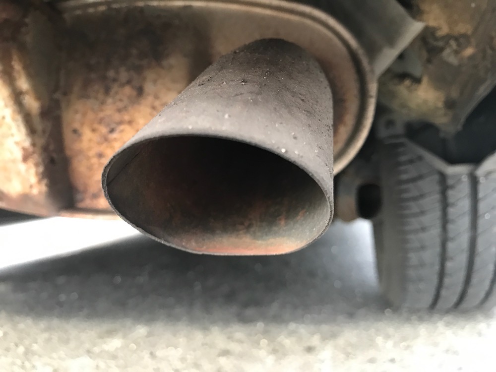
A rusty exhaust pipe.
Since environmental factors are not easy to predict or control, many engineers employ methods to protect their designs against atmospheric corrosion. For instance, depending on the environment, manufacturers may choose to use metals that are more naturally resistant to corrosion (like copper and aluminum) over others (like steel and iron). Other forms of protection include applying a protective coating to the design, such as a less noble metal (e.g., zinc-galvanized steel, tin-plated copper); paint; or anticorrosive material.
Reducing Corrosion via Cathodic and Anodic Protection
Another strategy for reducing atmospheric corrosion is to employ cathodic protection. A metal in contact with an electrolyte has cathodic areas where oxidation (protection) occurs and anodic areas where reduction (corrosion) occurs. The metal that is corroded is typically oxidized, and the electrons that are released are involved in cathodic reactions. While techniques vary, cathodic protection involves supplying electrons to the metal from an external source (like electric current). Cathodic protection is useful for common environments, such as where the metal would be exposed to water.
For example, by applying a metal coating such as in zinc-galvanized steel, the zinc will become an anode, since it is less noble, and protect the cathodic steel from corrosion whenever the steel is exposed to an electrolyte through damage in the zinc layer. There are other methods of cathodic protection, such as using sacrificial anodes or impressed current, but these methods are only reliable when the object is submerged in the electrolyte (e.g., water).
In certain environments, anodic protection can also be used. This method involves biasing the metal into a passive region by applying a controlled, small anodic current. This current will create a thin, passivating film layer that “chokes” the anodic corrosion reaction. It is commonly used in extremely corrosive environments, such as when stainless steel is exposed to phosphoric acid.
Using COMSOL Multiphysics and the add-on Corrosion Module, engineers can evaluate cathodic and anodic protection, electrolyte potential, and corrosion reactions in a design. As an example, let’s take a look at a model of a busbar, a bar used to distribute power in buildings, vehicles, and more — thus subject to atmospheric corrosion in a number of different environments.
Simulating the Atmospheric Corrosion of a Busbar
The busbar in this atmospheric corrosion example is made up of several materials and parts:
- Copper flange
- Aluminum flange
- Zinc nut and bolt
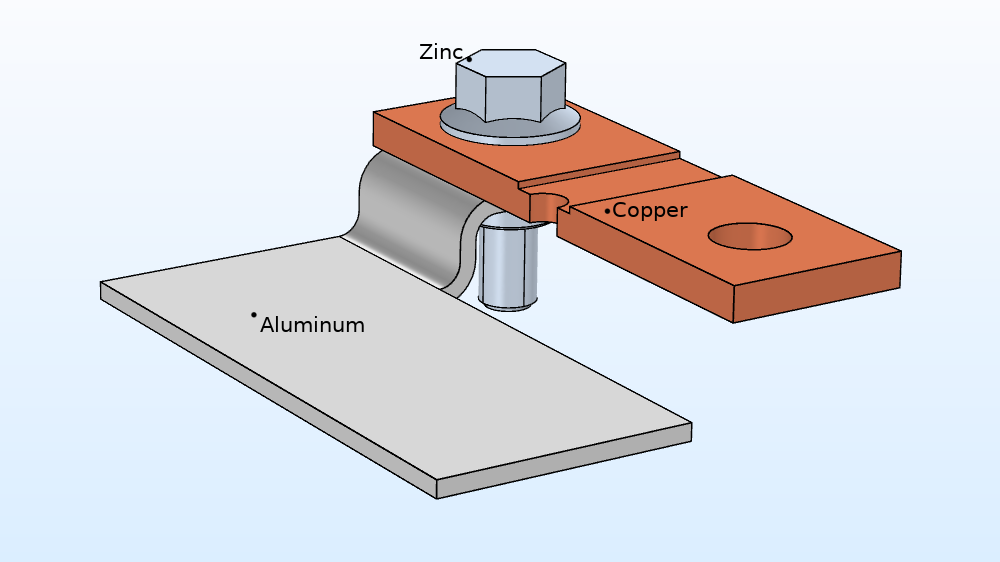
The busbar geometry, consisting of a copper flange, aluminum flange, and zinc nut and bolt.
Each of these surfaces accounts for two reactions:
- Metal dissolution, where the reaction kinetics are described by an anodic Tafel expression
- Oxygen reduction, where the reaction kinetics are described by a cathodic Tafel expression
In this example, the latter reaction (the reduction) is restricted by the oxygen transport through the film, with the limiting current density being dependent on the film thickness, oxygen solubility, and oxygen diffusivity.
Once the geometry is set up, the busbar is exposed to humidified air to begin the corrosion process. First, you can use the Secondary Current Distribution interface to solve for the electric potential in the electrode domain. Then, you can use the Current Distribution, Shell interface to solve for the electrolyte potential in the thin electrode layer.
The thickness of the electrolyte film depends on both the salt load density and relative humidity, while the conductivity and oxygen solubility depend on the relative humidity of the surrounding air. To account for the dependence on the relative humidity, you can take the same expressions used in the general Atmospheric Corrosion model to obtain the electrolyte film thickness, electrolyte conductivity, and oxygen solubility. The oxygen diffusivity is assumed to be constant.
Evaluating the Simulation Results in COMSOL Multiphysics®
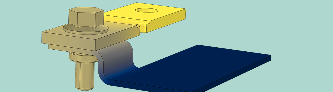
First up in the results is the baseline electric potential variation in the different types of metal, which can help you determine which areas are more prone to corrosion. In the left image below, you can see that the applied current (100 A) causes a potential drop of about 2.5 mV over the busbar.
Next, you can examine the difference between the electric potential in the metal and the electrolyte film potential (shown below on the right as the variation in the electrode potential versus adjacent reference), which shows how atmospheric corrosion affects each type of metal. Notice how it’s positive over the copper flange (red) and negative over the zinc nut and bolt (light blue) and aluminum flange (dark blue), indicating that the copper is more noble than the other materials, which are more likely to corrode in this model.


Electric potential variation in the busbar (left). Electric potential in the metals versus electrolyte film potential (right).
Now, let’s look at the electrolyte potential variation in the electrolyte film, the results of which can be seen below. By examining this variation in the film covering the busbar, you can get an idea for where the reactions are likely to occur for the anodic and cathodic areas.
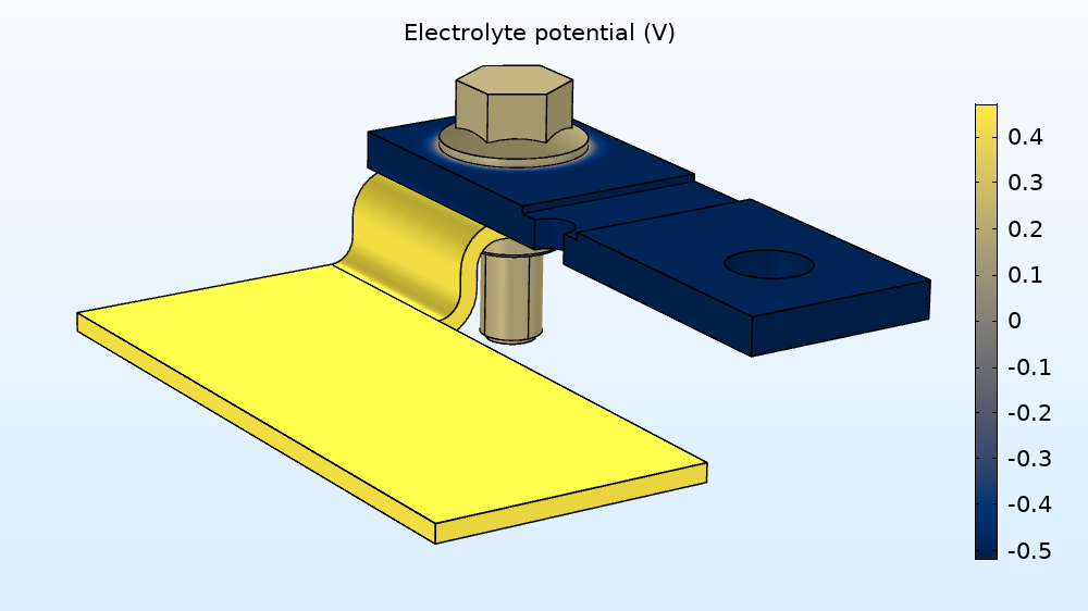
Electrolyte potential obtained in the electrolyte film covering the busbar.
Studying the Anodic/Metal Dissolution Reaction
To analyze the metal dissolution reaction, you can start by evaluating the local current for the density variation. As shown below, this reaction occurs mostly around the intersection between the copper flange and the zinc bolt (at the zinc surface) and also between the copper and aluminum flange at the aluminum surface. These results indicate that, as expected, the areas of localized corrosion occur between two dissimilar metals as well as the least noble metal.
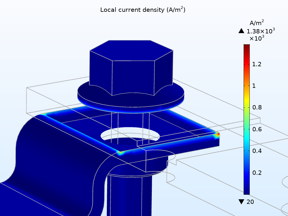
The local current density for the metal dissolution electrode reaction over the exterior surfaces of the busbar.
Studying the Cathodic/Oxygen Reaction
In the results for the cathodic reaction, you can see that the oxygen reduction occurs on the aluminum and zinc surfaces. Here, it is clear that the transport of oxygen is limiting the corrosion process because the magnitude of the local oxygen reduction current density is close to the limiting current density.
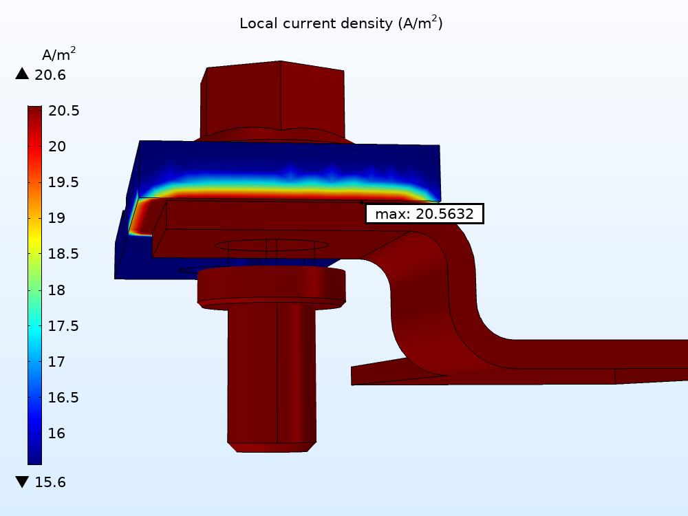
The local current density for the oxygen reduction electrode reaction over the exterior surfaces of the busbar.
After studying the corrosion process and figuring out where each type of reaction is likely to occur, engineers can design busbars with better protection from atmospheric corrosion with various environmental conditions in mind.
Next Step
To examine the atmospheric corrosion process yourself, you can click the button below to try out the busbar model featured here. Doing so will take you to the Application Gallery, which has documentation for this example and the related MPH-file.


Comments (0)