

Modular orthopedic devices, common in replacement joints, allow surgeons to tailor the size, material, and design of an implant directly to a patient’s needs. This flexibility and customization is counterbalanced, however, by a need for the implant components to fit together correctly. With parts that are not ideally matched, micro-motions and stresses on mismatched surfaces can cause fretting fatigue and corrosion. Researchers at Continuum Blue Ltd. have assessed changes to femoral implant designs to quantify and prevent this damage.
Simulating Loads in a Cyclic Gait
Take a few steps and see how your hips rotate. You’ll find that your body weight is continuously shifting between the left and right sides, while your legs bend, swing, and then straighten out with each step. Thus, a good modular hip replacement system will need to be able to freely allow for the natural motions of the human body — walking, running, or going up and down stairs. In addition to this, it has to be durable enough to take the continually changing, and sometimes excessive, loads placed on it during these movements, while being comprised of lightweight materials that fit and interact well with the body.
Modular implants often include stems, heads, cups, or entire joint systems. A range of materials from steel and titanium alloys to polymers and ceramics offer the surgeon many options depending on the needs of the patient. However, material and geometric selections affect the amount of wear and tear that will occur over time, so certain combinations of components are better than others. With so many different factors at play, it is not surprising that these assemblies require tight tolerances and the right material combinations to function properly and last a lifetime.
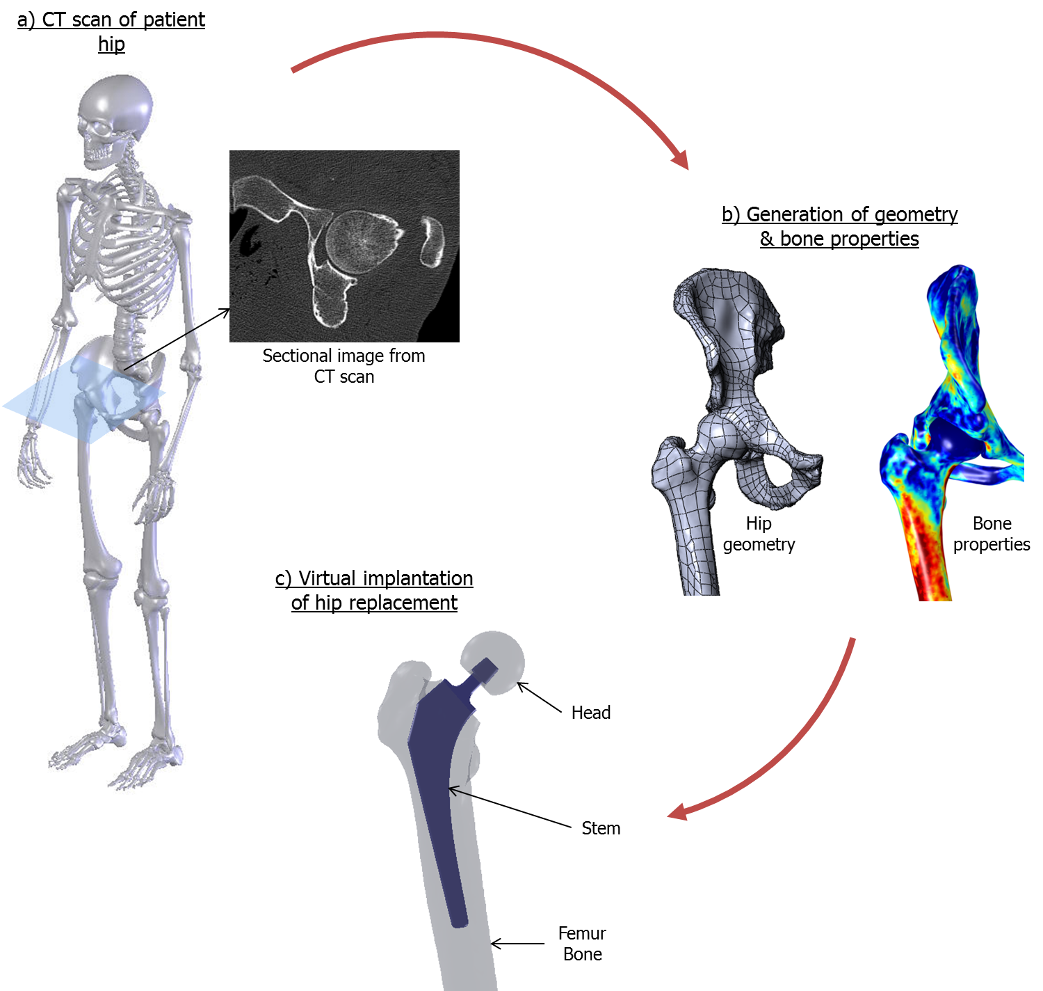
Virtual implantation of hip replacement in resected patient femur.
Studying how a modular combination of parts will behave under dynamic loads and stresses is a crucial part of the design and decision-making process. In order to understand the available combinations better and aid medical professionals in decisions, engineers at Continuum Blue have modeled three combinations of modular femur stem and head implants to investigate the fretting fatigue; the fatigue wear caused by the repeated relative sliding motion of one surface on another.
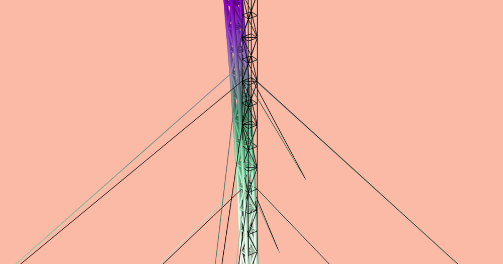
The femur head contains an angled channel for the neck of a femur stem, which in turn must be tapered correctly to fit the channel. The engineers studied three different geometric configurations using different materials for the head and stem to determine which of the three was best for minimizing fretting fatigue.
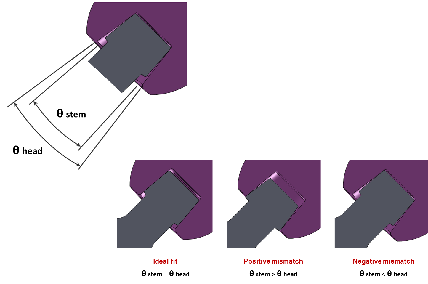
Different stem and head configurations with an ideal fit, positive mismatch, and negative mismatch.
Using kinematic load data from Bergmann et al. and based on averages from four patient sets, Continuum Blue created a COMSOL Multiphysics simulation to analyze the cyclic loading on a femur head. They used their model to determine the loading at different points during a walking gait cycle, knowing that the load would change at different locations in the rotation, and validated their results against the kinematic data.
Simulation results showing the dynamic loads and stresses during the gait cycle.
Stress and Fit: Which Option Will Last the Longest?
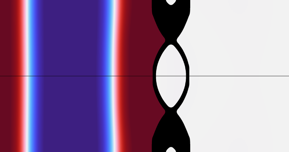
Material fatigue can be determined by studying the mean stress and stress amplitude that occur during the cyclic loading of the joint. Like the loading in the femur head shown earlier, the stresses in the femur stem will change over the course of a gait cycle. With regular leg movements, the stresses observed will take on an oscillation that reflects the repeated motion of the person walking.
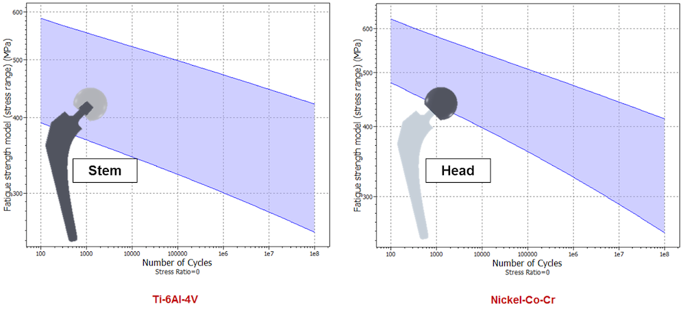
SN curves for the titanium stem and cobalt chromium head used in the study.
Continuum Blue assessed the three configurations with two different materials: a cobalt chromium alloy for the head and a titanium alloy for the stem of the modular implant. For each material domain, they calculated the stresses observed over a single gait cycle and related these to both the SN curves of the material and the micro-motions of the contact surfaces. This allowed them to predict the number of cycles the device could undergo before fretting fatigue became an issue.
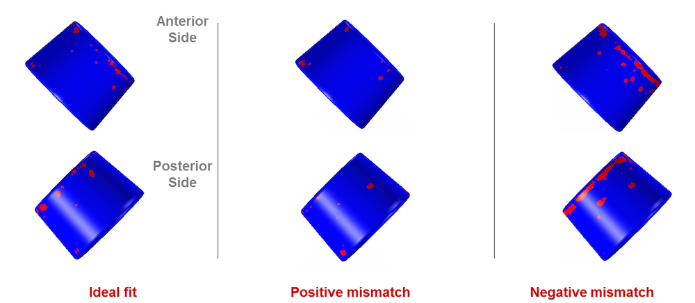
Areas where fretting fatigue occurs over gait cycle for each configuration.
Their results showed a surprising fact: the “ideal” fit, where the femur head channel is exactly aligned to the sides of the femur stem, was not found to be the best configuration for minimizing fretting fatigue. Rather, the configuration with a slight positive misalignment turned out to be a better choice, exhibiting lower stresses and overall fretting fatigue.
Through their simulation, Continuum Blue was able to predict the stress, contact pressure, and areas most susceptible to fretting fatigue at different points in a gait cycle. There are many other factors that will be accounted for in future research, such as the sensitivity of the implant to varying degrees of misalignment; additional designs and geometric changes; different materials; and the effects of surface finishes, coatings, or roughness that may impact the results. However, their modeling work offers a unique promise for evaluating the lifetime of a modular implant device. It was validated as an accurate way to predict the wear and tear that will occur for these three configurations of the implant. If you ever need a joint replacement analysis — you’ll know who to call.
Download the Presentation
- COMSOL Conference 2012 presentation: “Fretting Wear and Fatigue Analysis of a Modular Implant for Total Hip Replacement“

Comments (0)