

Truck-mounted cranes are often used for load handling. In many cases, this involves carrying heavy materials, which can exert large forces on various parts of the crane. See how simulation can help identify the impact of these forces and enhance the crane’s operation.
A Mobile Machine
By design, cranes offer a mechanical advantage, lifting and lowering heavy materials that require strength beyond that of a human. In many applications of this machine — from construction to electric line maintenance — a favorable feature is mobility. Truck-mounted cranes are free to move in various directions as well as travel on highways, which can help avoid the need for additional transport equipment.
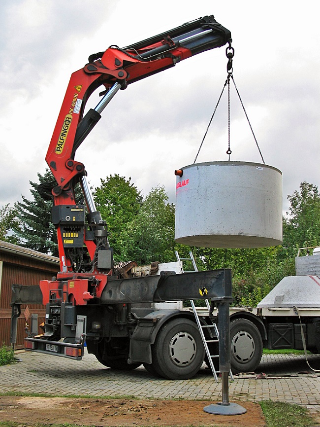
An example of a truck-mounted crane. (“A truck-mounted crane from Palfinger (Austria). The concrete component (build in Germany) is a small sewage treatment plant for a house with up to four residents.” by TM — Own work. Licensed under Creative Commons Attribution-Share Alike 2.0 Germany, via Wikimedia Commons.)
In these types of cranes, there are several hydraulic cylinders that control the motion of the crane as well as many other mechanisms. When handling heavy loads, the components are subjected to large forces. Through simulation, we can explore the impact of these forces during the machine’s operating cycle, determining ways to enhance its performance by building a more efficient design.
Performing a Rigid Body Analysis of a Truck-Mounted Crane
Combining the Multibody Dynamics Module with the Structural Mechanics Module, the Truck Mounted Crane model analyzes the forces on the cylinders and hinges of a crane during an operating cycle. The crane geometry, which is imported from a CAD model, is comprised of 14 parts that move in relation to one another.
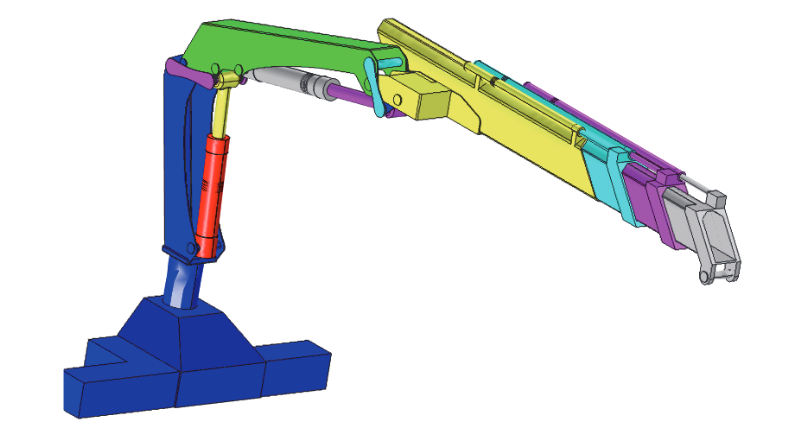
Geometry of the truck-mounted crane.
The figure below provides a more detailed overview of the crane link mechanisms, followed by a table defining the individual components.
| Part | Color |
|---|---|
| Base | Blue |
| Inner boom | Green |
| Outer boom | Yellow |
| Telescopic extensions | Cyan, Magenta, Gray |
| Boom lift cylinders | Red, Gray |
| Boom lift pistons | Yellow, Magenta |
| Inner link mechanism | Magenta, Black |
| Outer link mechanism | Cyan, Blue |
In this example, there are two loads applied — self weight in the negative z-direction and a payload of 1,000 kg at the crane’s tip. The operating cycle consists of lifting the payload from a position that is far away and placing it below the crane. The load is initially moved upwards and then drawn inwards to a position that is close to the crane. The plot below depicts the crane tip’s trajectory during the operating cycle.
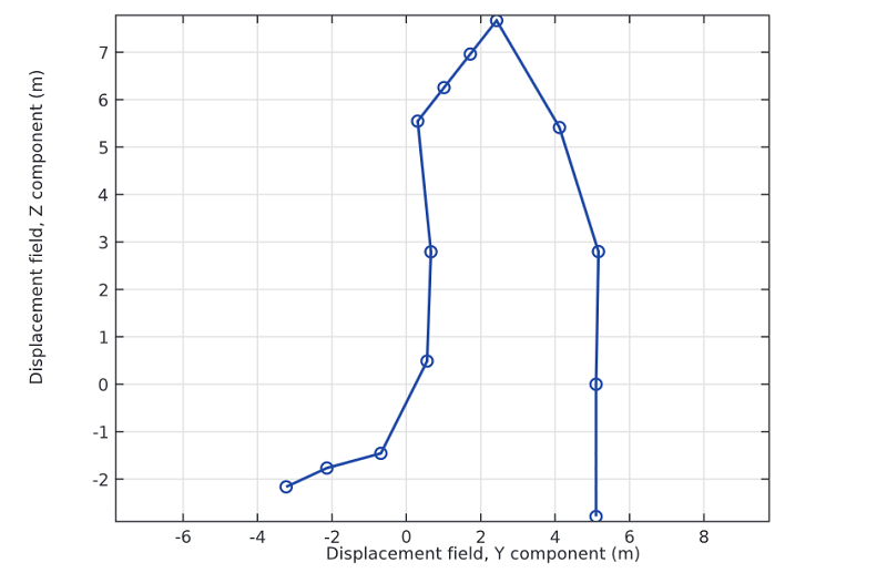
Crane tip trajectory during operating cycle.
In reality, the crane is operated by controlling three cylinder lengths — the inner cylinder, the outer cylinder, and the extension cylinders. The inner cylinder raises the inner boom, the outer cylinder regulates the angle between the inner boom and the outer boom, and the extension cylinders determine the reach of the extensions. Here, the angles of the booms are used as parameters rather than the cylinder lengths, as this method is more convenient.
The Results
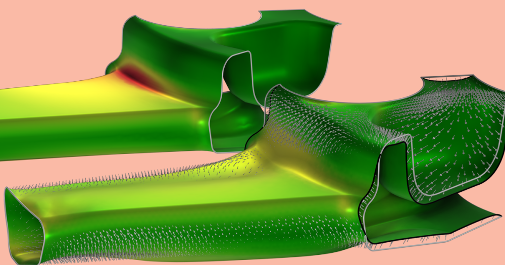
The image below illustrates the 9th position of the operating cycle, which features an inner boom angle to the horizontal of 45°, a -30° angle between the inner and outer boom, and a total extension of 1.5m.
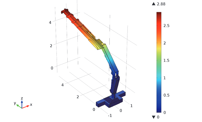
The crane during the 9th position of the operating cycle. The color shows the total displacement of the crane components.
We can now address the impact of the forces on various parts of the crane. In each of the following graphs, the solution number correlates to the position of the crane. Initially, the crane picks up a load in an extended position and then, at the final solution, releases the load close to its own position.
Let’s begin with the forces in the cylinders controlling the boom. Here, the compressive forces are positive. As can be expected, when the payload is far from the crane base, the cylinder forces are greater. The maximum force during the operating cycle determines the required cylinder capacity.
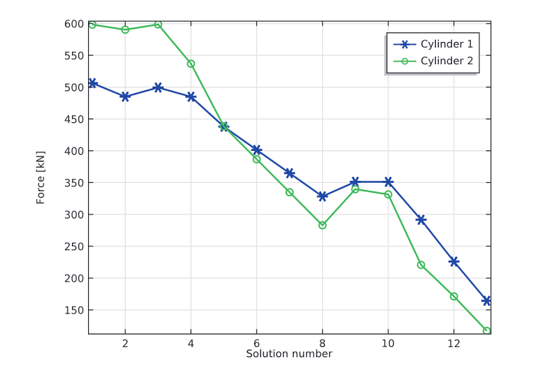
Forces in the cylinders controlling the boom.
The next graph highlights the forces in the extension cylinders. As in the previous case, a compressive force is defined as positive. Because they have to carry the weight of extension segments a further distance, the inner cylinders endure greater forces.
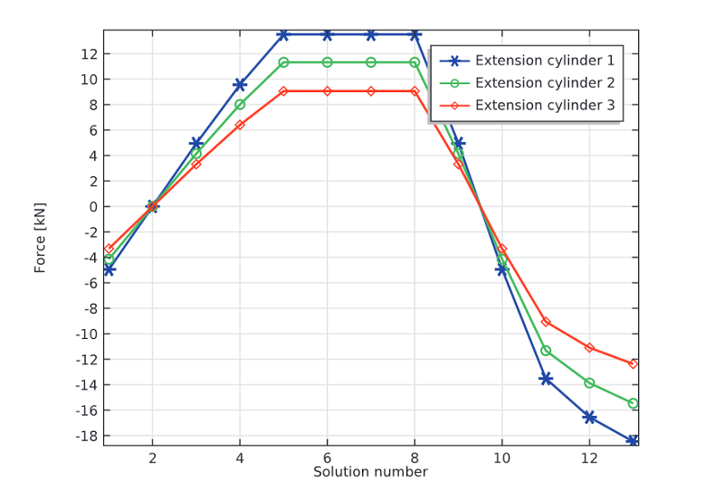
Forces in the extension cylinders.
Finally, we can observe the forces acting on the hinges between the main parts of the crane. This same tactic can be used to analyze the forces within the connections between any parts of the crane. The results below are a valuable resource in the structural dimensioning of such details.
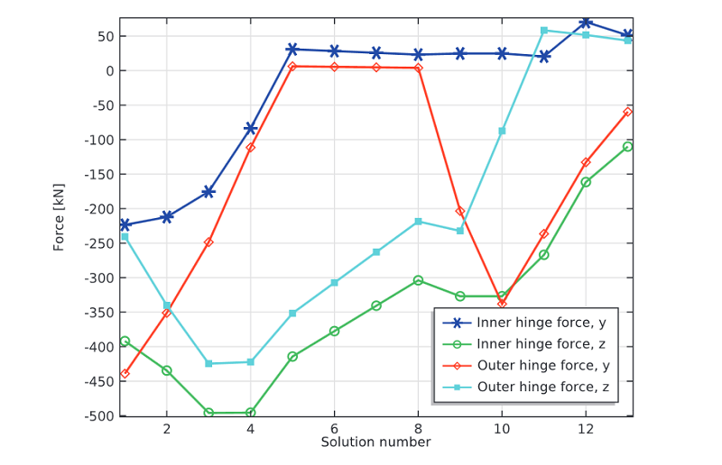
Forces on the hinges.
Targeting a Particular Mechanism in the System
We can now take things a step further and use the Optimization Module to enhance the crane link mechanism. This can be accomplished through the Optimization of a Crane Link Mechanism model, a continuation of the Truck Mounted Crane model. In this case, the focus is on reducing the cylinder force that is necessary to haul a particular payload in a worst-case load cycle scenario.
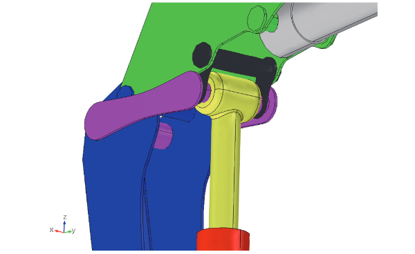
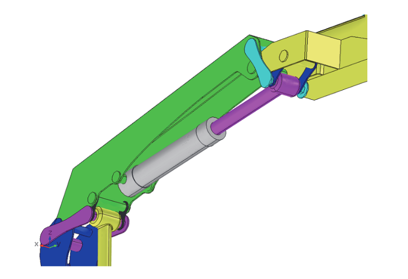
A detailed look at the link mechanisms.
The table below identifies each of the parts and their colors considered in this model.
| Part | Color |
|---|---|
| Base | Blue |
| Inner boom | Green |
| Boom lift cylinder | Red |
| Boom lift piston | Yellow |
| Link mechanism | Magenta, Black |
Since this example is designed to test for the worst-case scenario, the operating cycle is chosen so that the link mechanism will experience as much force as possible. To ensure this, the inner boom is raised to its highest position, the telescopic extensions are extended as far out as possible, and the angle of the outer boom is selected to ensure that the crane tip is as far out as it can be. The same loads from the original model are applied.
Within this optimization problem, the positions of three axles can be changed. These include the axle that connects the first link arm to the base, the axle that connects the second link arm to the boom, and the axle that connects the two link arms and the hydraulic cylinder’s piston.
Comparing Designs
Now let’s compare our results. The first graph below shows the variation of the cylinder force during the operating cycle. Here, we compare the maximum cylinder force during the operating cycle, which determines the capacity of the hydraulic cylinder.
In comparison to the original design, the optimized version enables a reduction in the maximum force from 597 kN to 413 kN — that’s a 31% decrease, a sizable improvement! With this enhancement, the allowed payload can become greater; the decreased forces will enable the link mechanism to meet stress criteria more easily.
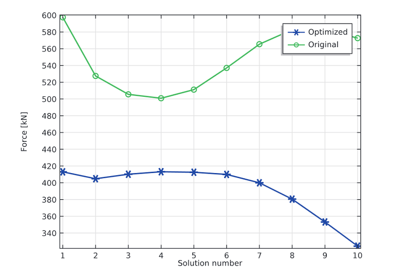
Comparing the cylinder forces in the optimized and original designs.
The second plot illustrates the y- and z-components and the magnitude of the force acting on the axle that forms the hinge between the base and the boom. As indicated by the results below, the total force of the original design is greater than the total force of the optimized design.
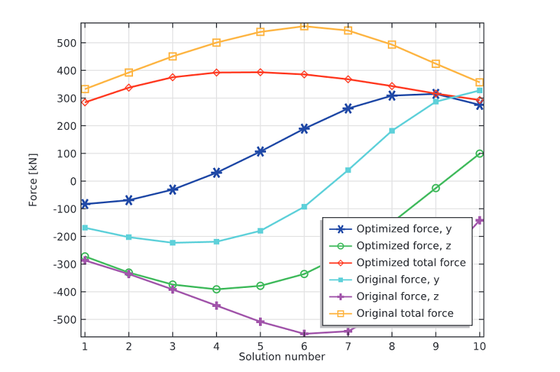
Forces acting on the axle in the optimized and original designs.
Summary and Model Downloads
With COMSOL Multiphysics version 5.0, we introduced two new models designed to analyze the interactions between different components of a truck-mounted crane and evaluate the role of optimization methods in enhancing these mechanisms. These examples demonstrate how simulation can be used to investigate the impact of loads on such complex mechanical systems and how this knowledge can be applied to developing a stronger design.
Download the models featured here:
One last thing… We’re in the process of creating an app based on this model. Stay tuned for that.


Comments (0)