Modeling of Electro-Thermal Microbolometer for Thermal Imaging
A Microbolometer is a specific type of uncooled infrared radiation detector used in thermal cameras, which converts the incoming energy into a proportionate electrical signal, which is then amplified, processed and displayed, typically on the thermal camera’s LCD viewer. The main principle of operation of a microbolometer is a thermally sensitive layer which is exposed to incident electromagnetic radiation. Energy is absorbed and the temperature of the material rises, and there is a concomitant change in resistance. The resistance change information is then electrically transferred to the read-out integrated circuit (ROIC) for further processing. Such a Micro Electro Mechanical System (MEMS) is extremely appealing for reducing the size, cost and power consumption of infrared sensors used in a range of applications without sacrificing performance and functionality.
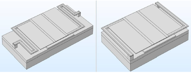
In this research, an electro-thermal model of MEMS microbolometer has been produced by taking into account the incoming infrared energy and Joule’s heating sources. The influence of different arms dimensions and shapes on device performance is investigated. Within this two different microbolometer pixels’ geometries have been designed, using the COMSOL Multiphysics® software, and examined. Due to the low signal voltage from microbolometer devices, the most important parameter to consider during design and optimization is responsivity, which is strongly related to the total capacitance and thermal conductance. Therefore, in the presented model the deciding factors for higher performance have been computed and then have been checked using an analytical method. The temperature distribution at any given time provides valuable information about the microbolometer’s performance and behaviour. The temperature distribution across the length of the Long-leg and Short-leg microbolometer structures was simulated. The Long-leg geometry is characterised by lower conductance and higher capacitance, compared to the Short-leg structure.
The calculation results show that the pixel’s responsivity is strongly affected by dimensions of the geometry. For Long-leg microbolometer the obtained responsivity was twice as high as for the Short-leg microbolometer structure. This means that by increasing the microbolometer legs length by 30 μm (53%) each, we have gained 100% of responsivity enhancement, even though there was just a slight difference in total capacitance of 0.04 [J/K] between Long-leg and Short-leg geometries.
Therefore, the supporting legs should be as long as possible and the width and thickness should be as small as possible. Making very long legs with minimum width and thickness have some experimental difficulties, but it has been proven that by a good design, it’s possible to strongly improve the microbolometer performance.
Herunterladen
- nowicki_poster.pdf - 0.48MB
- nowicki_abstract.pdf - 0.06MB