

In electrochemistry, it’s common to use a microdisk as the working electrode in an analytical technique known as cyclic voltammetry. However, unlike with a macroelectrode, diffusion at a microelectrode occurs very fast on the timescale of the experiment. To simplify the analysis, we can use an approximation that assumes the microdisk has stationary diffusion properties on the timescale of the voltammetry study — eliminating the need for a time-dependent model.
What Is Cyclic Voltammetry?
Cyclic voltammetry is an electrochemical technique in which the potential is swept repeatedly — for example, between a start and end potential — and the resulting currents are measured. What makes voltammetry beneficial in many systems is the diversity of information a single scan can provide about the system’s behavior, such as the absorption-desorption process at the electrode surface.
Engineers use different types of electrodes, including microdisk electrodes, as the working electrode in cyclic voltammetry. A microdisk electrode is a disk electrode with a radius of the order of microns that is embedded in an insulator whose surface is flush with the electrode. Due to their small size, microdisk electrodes have diffusion layers, which are large in comparison with their size, and small overall currents, which help them achieve steady-state conditions. The smaller the electrode, the less time it takes to attain a steady state. They also have high scan rates with limited distortion. The advantage of using smaller-sized electrodes to study voltammetry is that they have mass transport properties that can maximize the current density — enabling scientists to observe electrochemical behavior that just wouldn’t be possible to see on a macroelectrode.
Along with the working electrode with which the solution is probed, a standard cyclic voltammetry experiment uses a cell fitted with a counter electrode, which completes the circuit, and a reference electrode, which is not polarized, so its potential is assumed to be constant. Using the reference electrode potential, the electrode potential of the working or counter electrode can be measured. A supporting electrolyte is added to increase the conductivity of the solution.
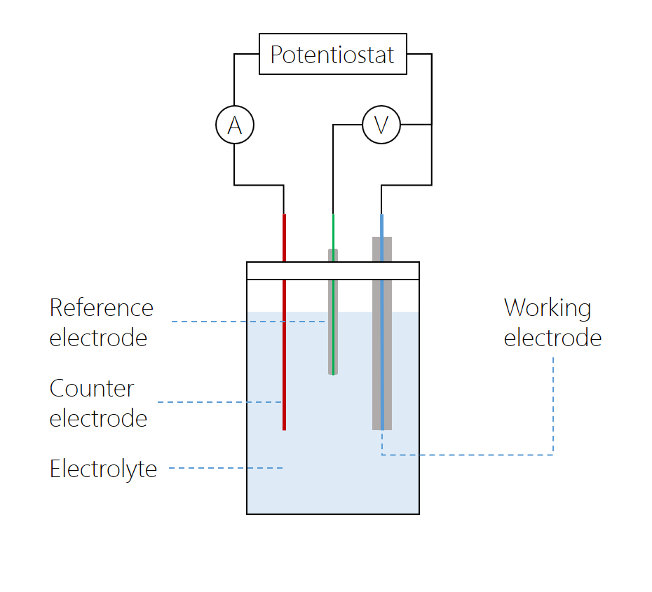
The microdisk electrode is the working electrode, with a counter electrode positioned at a relatively large distance. The reference electrode is connected to the working electrode over a high-impedance voltmeter, while the current between the working and counter electrodes is measured over a low-impedance amperometer. The potentiostat varies the potential over the cell. In modern potentiostats, the voltmeter and amperometer are built in.
The cyclic voltammetry system consists of a potentiostat, which keeps the working electrode potential at a constant level relative to the reference electrode; a current-to-voltage converter; and a data acquisition system that generates the voltammogram. A cyclic voltammogram can have many different shapes and is characterized by plotting current density against applied potential. In the case of a single reversible electrode reaction measured using a planar electrode, the graph takes on a “double peak” shape. However, the shape of the graph depends on the electrode and the composition of the electrolyte.
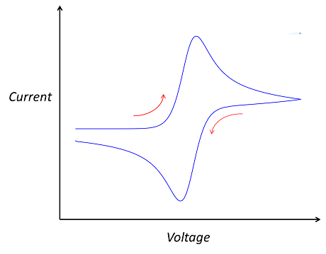
The double-peaked shape of a typical cyclic voltammogram.
Modeling Voltammetry at a Microdisk Electrode in COMSOL Multiphysics®
The model consists of a 2D axisymmetric domain. The Infinite Element domain feature in the COMSOL Multiphysics® software is used to extend the bulk solution of the concentric region to infinity. This is a suitable approximation, since we’re assuming that the electrochemical cell is several orders of magnitude larger than the electrode.
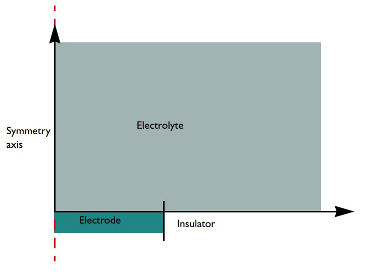
A schematic of the microdisk electrode model geometry with surrounding electrolyte. Note that the configuration is flipped upside-down compared to the cell in the first figure. In this case, the electrode surface is facing upward while the figure above shows the electrode surface facing downward (the norm in real configurations). Gravity is not accounted for in the model, so in this context, the flipping does not matter for the model results.
As mentioned above, we add a supporting electrolyte to increase the conductivity of the electrolyte. As a significant amount of supporting electrolyte has been added, it can be assumed that the electrolyte potential is a constant, and in this case, set to φl = 0. To simulate the electrochemistry of this situation, we use the Electroanalysis interface, which implements the chemical species transport equations for the reactant and product species of the redox couple. The diffusion equation describes the chemical transport of electroactive species A and B at a steady state.
Next, we apply boundaries to the bulk, insulating the surface, electrode, and species as well as accounting for the electrochemical processes involved. Species A, for instance, is reactant at the electrode boundary and when it is oxidized, it loses an electron and forms the product B.
After the boundary equations are implemented, we set up the study. In this example, we don’t need to perform a time-dependent analysis. This is because we use a common approximation where we assume the microelectrode has stationary diffusion properties on the timescale. The steady-state result is accurate, which means we can use a stationary study. We use a parametric sweep to get current densities at the potentials applied in the voltammetric sweep under the quasistatic approximation.
Examining the Results
The plot below shows the stationary concentration profile around a microdisk electrode (note the distinct shape of the 2D cross section). The concentration profile is hemispherical at large distances from the electrode, but the flux is elevated close to the disk edge. For fast kinetics, the concentrations on the electrode surface are uniform, leading to a slightly nonuniform flux distribution over the electrode’s surface, which means that the reaction is also slightly nonuniformly distributed.
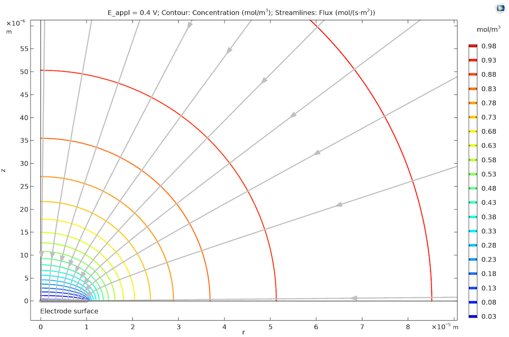
The concentration profile for transport-controlled oxidation of species A at a microdisk electrode. Note that we have rotational symmetry at r = 0. The streamlines show that the flux, hence the reaction rate at the microdisk electrode surface (highlighted in gray), is slightly higher at its edge (right) compared to the center (left).
Next, we can examine the cyclic voltammogram that shows the relation between the electrode kinetics and diffusion, or chemical species transport, where the current density is limiting.
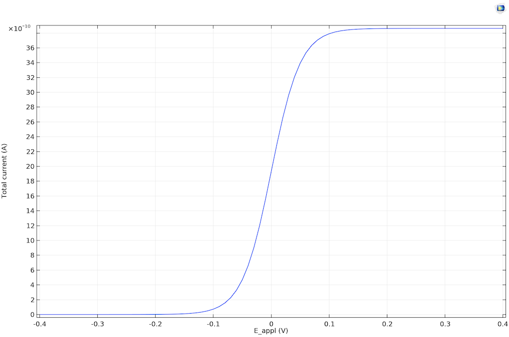
The steady-state cyclic voltammetry recorded at a microdisk electrode.
The current density becomes limiting because of the finite rate of diffusion. It is 0 (not limiting) when E < Eeq. At E < Eeq, only reduction is possible, and since there are no oxidized species in the electrolyte, nothing happens. When the oxidation reaction accelerates so that it’s fast enough to consume a significant reactant at the electrode surface, the current becomes limited by the rate of transport A toward the working electrode. This transport-limited current is constant in time, since the diffusion layer is equilibrated.
We don’t see negative current for the voltammetry for the steady state because the product species is dispersed to the bulk solution. Equilibration between the bulk and the electrode surface is achieved due to the fast diffusion on the timescale. The reaction is therefore always oxidative because of the absence of product in the bulk electrolyte.
Next Steps
If you’d like to try this example yourself, click the button below. Doing so will take you to the Application Gallery, where you can download the model documentation and MPH file for the Voltammetry at a Microdisk Electrode model.
Further Reading
Learn more about electrochemistry and voltammetry on the COMSOL Blog:

Comments (0)