

Branch line couplers, a type of 90-degree or quadrature hybrid coupler, are popular because they are simple to fabricate and easy to design. They are passive devices commonly used in single-antenna transmitter systems and I/Q signal splitters/combiners. Let’s look at the basics of how this type of coupler works and some of its important design aspects.
About Branch Line Couplers
Branch line couplers are used for either splitting or combining power. This type of coupler is made up of two sets of coupled ports with a phase difference of 90° between them. The power enters through one input port and is then divided equally between two output ports. The fourth port is isolated.
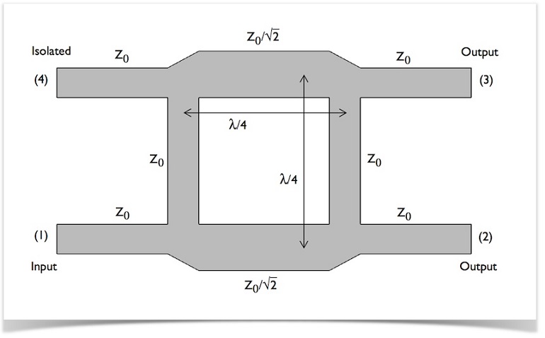
Geometry of a branch line coupler. In the image, transmission lines are horizontal and branch lines are vertical.
Branch line couplers are designed to be symmetrical, as shown in the geometry above, which means that you should be able to select any of the ports for the input power and still achieve the same behavior. In the geometry depicted above, the bottom-left port is chosen as the input port, but we could just as well have swapped the input and isolated ports, or flipped it so the two outputs were on the left and the input and isolated ports on the right.
In the case of single-antenna transmitter/receiver systems, you have a transmitter at the input port (1), a 50 ohm termination at port (2), an antenna at one output (3), and a receiver at the isolated port (4). Here, the power moves in quadrature phases from the transmitter to the antenna, and then, the antenna sends a signal back to the receiver. The receiver and transmitter are unaffected by each other.
Important Design Aspects
There are a few important criteria your branch line coupler design will need to meet in order to function:
- High isolation
- Should be as high as possible, but note that it can never actually be 100%
- Ability to set any ports as input, isolated, and outputs and still achieve the same frequency output
- Quadrature phase difference (S-parameters)
An Example Model
If you want to design an accurate branch line coupler, you can use COMSOL Multiphysics along with the RF Module to set up a model. To help you get started, we have included an example model in both the Model Gallery online and the Model Library in the RF Module (you can find it under “Passive Devices”).
Following the instructions in the model documentation, you will be able to compute the S-parameters and evaluate the phase difference to ensure it is 90 degrees. You will also be able to analyze the matching, isolation, and coupling at the ports around the operating frequency.
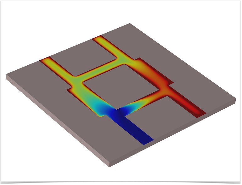
Plot showing that the input power (red) is divided equally between the two output ports (yellow). The isolated port is blue.
Further Reading
- Learn how to build the Branch Line Coupler model
- You may also be interested in the:

Comments (0)