Generatives Design für die Entwicklung von Wasserstoff-Brennstoffzellen
Als Alternative zu batterieelektrischen Fahrzeugantrieben treibt Toyota die Entwicklung von Wasserstoff-Sauerstoff-Brennstoffzellen voran, um Autos, Lastwagen und sogar ganze Städte mit Strom zu versorgen. Das Toyota Research Institute of North America (TRINA) hat eine simulationsbasierte Methode entwickelt, um den F&E-Prozess von Strömungsfeldplatten für Brennstoffzellen zu beschleunigen.
Von Alan Petrillo
April 2023
„Electrify everything.“ Unter denjenigen, die die Abhängigkeit der Welt von fossilen Brennstoffen verringern wollen, ist dieser Satz zu einer Maxime geworden. Wir können das Gebot der Elektrifizierung überall um uns herum in Aktion sehen, denn gasbetriebene Hybrid-Elektrofahrzeuge (HEVs) und Batterie-Elektrofahrzeuge (BEVs) sind inzwischen ein vertrauter Anblick auf den Autobahnen. Doch während viele Autohersteller die Produktion von HEVs und BEVs hochfahren, widmet sich ein Unternehmen der Entwicklung von Elektroautos, die nicht primär auf Batterien als Energiespeicher angewiesen sind. Stattdessen transportieren diese Autos Wasserstoff, der in Verbindung mit dem Sauerstoff aus der Luft in einer Brennstoffzelle Strom erzeugt.
Das Unternehmen, das diesen alternativen Weg verfolgt, ist Toyota. Die Vermarktung von wasserstoffbetriebenen Fahrzeugen steht vor vielen Hindernissen, aber wenn es jemand schafft, die Welt auf brennstoffzellenbetriebene Räder zu stellen, dann könnte es der größte Automobilhersteller der Welt sein (Ref. 1). Toyota setzt große finanzielle, materielle und personelle Ressourcen für die Brennstoffzellenforschung ein, sieht die Entwicklung von Fahrzeugen aber nur als den Anfang einer langen Reise. Die Vision des Unternehmens geht weit über Autos hinaus - es sieht die Entstehung einer globalen „Wasserstoffgesellschaft“ voraus. In dieser Gesellschaft sollen Motoren, Heizungen und Generatoren, die mit fossilen Brennstoffen betrieben werden, durch Brennstoffzellen ersetzt werden, die elektrischen Strom aus Wasserstoff gewinnen. Toyotas Bemühungen, dieses Ziel zu erreichen, sind so weitsichtig wie die Wahl der japanischen Stadt Susono als Wasserstofftechnologie-Testgebiet und so zielgerichtet wie die Verfeinerung einer generativen Design-Methode zur Optimierung der Brennstoffzellenleistung.
Generatives Design durch Simulation
Das Toyota Research Institute of North America (TRINA) hat eine simulationsgestützte generative Design-Methode entwickelt und sie angewandt, um Mikrokanal-Strömungsfeldplatten zu entwerfen, die die Bewegung von fluiden Reaktanten in Mikroreaktoren wie Wasserstoff-Sauerstoff-Brennstoffzellen steuern. Während ein Großteil der Brennstoffzellenforschung und -entwicklung bei Toyota notwendigerweise der Geheimhaltung unterliegt, hat das TRINA-Team einen Artikel über ihren simulationsbasierten „inversen“ Designprozess in der Fachzeitschrift Chemical Engineering Journal veröffentlicht (Ref. 2). Die Anwendung dieses Prozesses auf Strömungsfeldplatten hat zu vier unterschiedlichen Mikrokanaldesigns geführt, die in Abbildung 1 dargestellt sind.
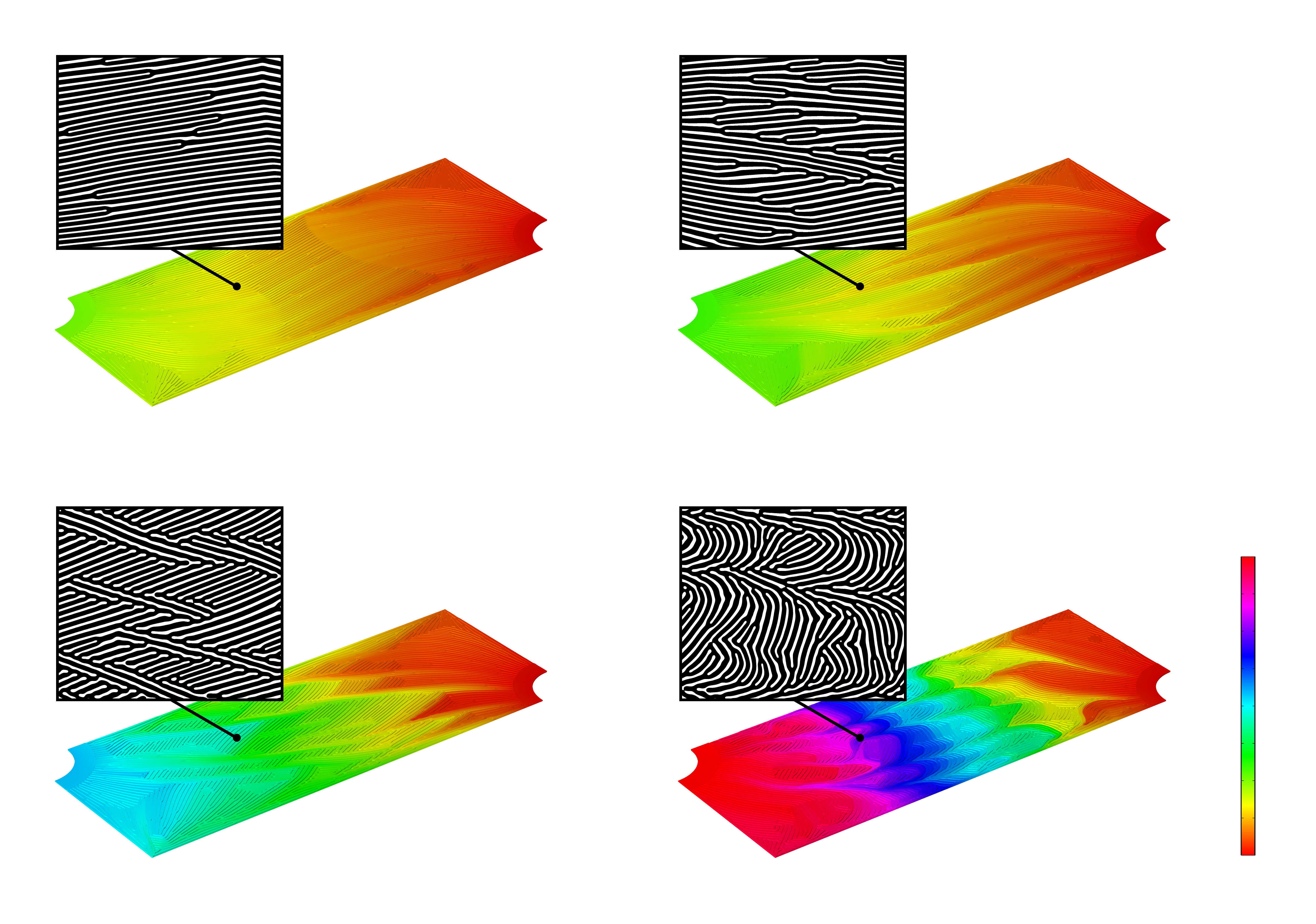
Jeder der vier Entwürfe hat seine eigenen Vorzüge und alle übertreffen die bestehenden Benchmark-Designs in Bezug auf die wichtigsten Kennzahlen. Genauso wichtig ist, dass sie ein Beispiel für die Stärken des Prozesses darstellen. TRINA hat gezeigt, wie generatives Design mithilfe von Simulationen Innovationen beschleunigen kann – selbst wenn das endgültige Ziel eines Projekts noch weit in der Zukunft liegt.
„Wir glauben, dass der inverse Ansatz die derzeitige Designpraxis revolutionieren kann“, sagt Yuqing Zhou, Wissenschaftler bei TRINA. „Wir ermöglichen den nächsten Schritt auf einer langen Reise, auch wenn wir nicht genau wissen, wohin diese Reise führen wird.“
Sauberere Optionen für Antriebsstränge
In Anbetracht dieser ergebnisoffenen Untersuchung ist es verständlich, dass Toyota seine jahrzehntelange Forschung im Bereich der Brennstoffzellen fortsetzt, auch wenn die meisten Autohersteller für Elektrofahrzeuge ausschließlich auf Batterieantriebe setzen. Wie der Vorsitzende Akio Toyoda es in einem Interview im November 2022 ausdrückte (Ref. 3): „Stellen Sie sich Toyota als ein Kaufhaus vor, das alle verfügbaren Antriebsarten anbietet.“

Eine Wasserstoff-Sauerstoff-Brennstoffzelle mag zwar wie eine exotische Art der Energieversorgung für ein Auto erscheinen (Abbildung 2), aber die Technologie selbst ist nicht neu und ihre Funktionsweise ist verlockend einfach. Abbildung 3 zeigt das Grundprinzip einer typischen Brennstoffzelle.
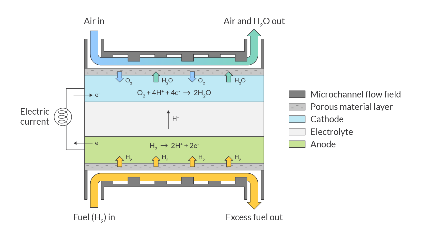
Wenn Wasserstoffgas durch die Anode strömt, trifft es auf einen Katalysator, der es in Wasserstoffionen und Elektronen zerlegt. Während sich die Wasserstoffionen durch den Elektrolyten bewegen, um die Kathode zu erreichen, bewegen sich die Elektronen durch einen Leiter außerhalb der Brennstoffzelle. Dieser elektrische Strom kann genutzt werden, um Arbeit zu verrichten.
Wenn das Sauerstoffgas aus der Luft über die Kathode strömt, trifft es auf die Wasserstoffionen und die zurückkehrenden Elektronen an der Oberfläche der Kathode. Hier spalten sich die Sauerstoffmoleküle und verbinden sich mit den Wasserstoffionen und Elektronen zu Wasser.
Der Weg eines Reaktanten durch eine Strömungsfeldplatte
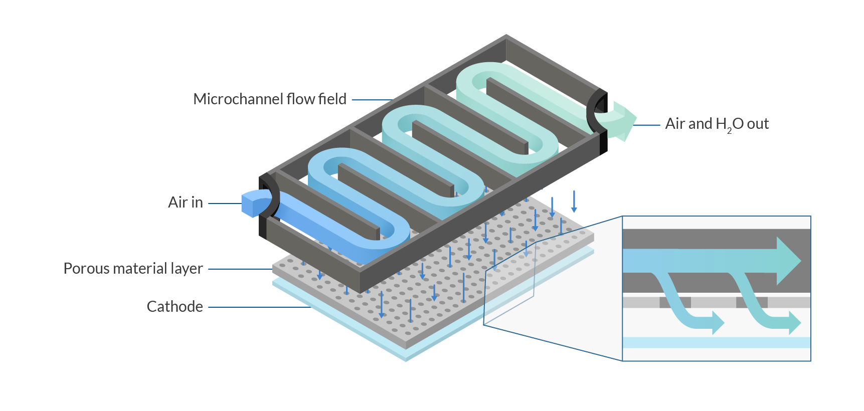
Solange Wasserstoff und Sauerstoff fließen, erzeugt eine Brennstoffzelle elektrischen Strom. Die Verteilung dieser essentiellen Gase wird von den Strömungsfeldplatten der Zelle gesteuert. Jede Platte besteht sowohl aus einer Mikrokanalstruktur als auch aus einer Schicht aus porösem Material. Während sich der Wasserstoff durch die Kanäle der anodenseitigen Platte bewegt, wird er auch durch die poröse Schicht zur Anode gedrückt. Währenddessen wird Luft durch die Strömungsfeldplatte auf der Kathodenseite der Brennstoffzelle geleitet. Luft und Wasser werden durch die poröse Schicht auf der Kathodenseite ausgetauscht, und die Platte leitet überschüssige Luft und Wasser vom Zellstapel weg. Abbildung 4 zeigt eine vereinfachte Nahansicht dieses wesentlichen Prozesses auf der Kathodenseite.
In ihrem Fachartikel zu diesem Projekt erklärt das TRINA-Team, dass „die Gleichmäßigkeit der Verweilzeit des Fluids oder der Verteilung des Fluidstroms und die Beziehung zum optimalen Wärmetransport direkt mit dem Design der Strömungsstruktur zusammenhängt, die für die angemessene Steuerung der chemischen Reaktionen von größter Bedeutung ist.“
Dementsprechend bestehen die beiden Hauptziele für das Design von Brennstoffzellen-Strömungsfeldplatten darin, den Fluidstrom durch das Mikrokanal-Strömungsfeld der Platte und durch die poröse Schicht zu maximieren, um der Elektrode ausreichend Reaktanten zuzuführen. Das erste Ziel kann als Ziel verstanden werden, den Widerstand gegen den Reaktantenfluss zu verringern, während das zweite Ziel darin besteht, die Umwandlung des Reaktanten und die Gleichmäßigkeit der Reaktion auf der gesamten Elektrodenoberfläche zu verbessern.
Inverses Design: Ein einfacheres Verfahren für komplexe formale Lösungen
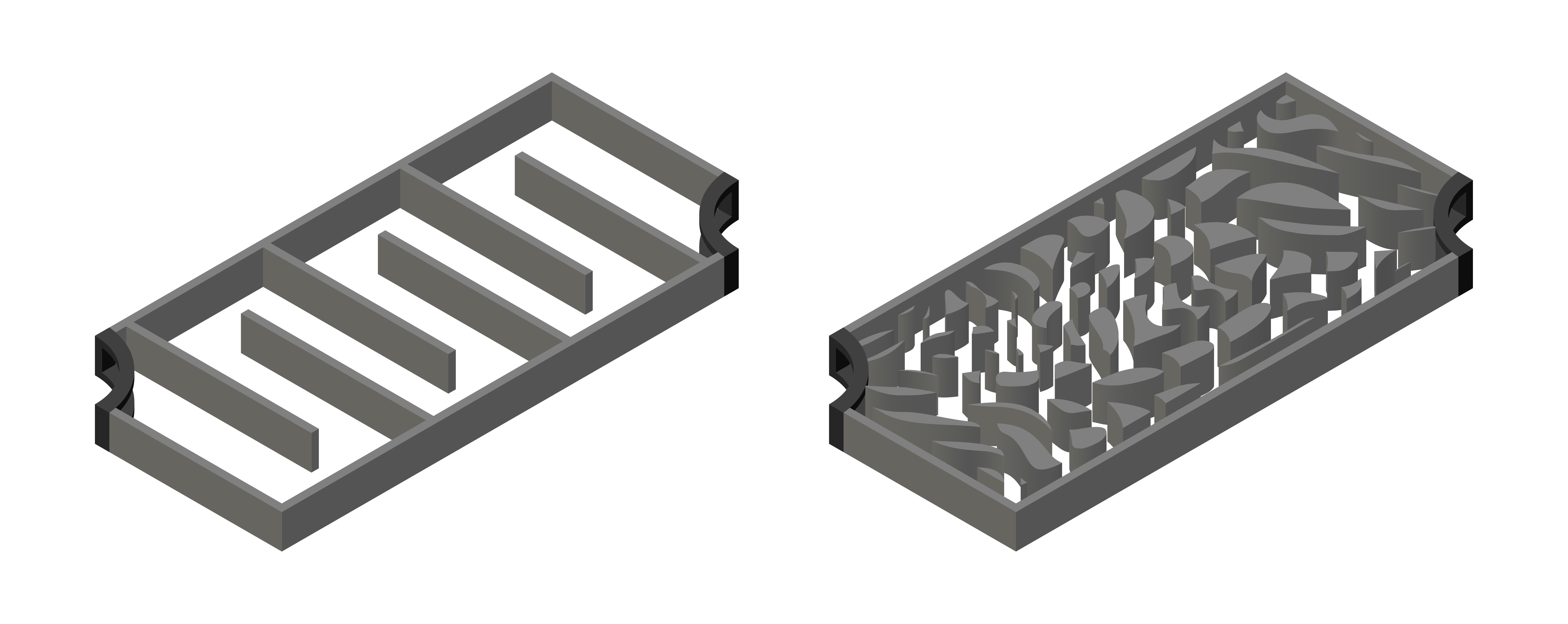
Die physische Anordnung der Mikrokanäle beeinflusst, wie gut eine Strömungsfeldplatte ihre Leistungsziele erfüllt. In der Vergangenheit folgten Mikrokanaldesigns einigen wenigen bekannten Mustern, wie zum Beispiel dem links in Abbildung 5 dargestellten Serpentinenmuster. Komplexere Formen könnten die Leistung verbessern, aber mit zunehmender Komplexität eines Designs steigt auch der Zeitaufwand für die Definition, Herstellung, Prüfung und Anpassung des Designs.
Zhou und seine Kollegen erkannten, dass sie, bevor sie versuchten, ihre Designs zu optimieren, zuerst ihren Designprozess optimieren mussten. Um eine komplexere (und leistungsfähigere) formale Lösung für ihr Problem zu finden, entwickelte das TRINA-Team seine simulationsgestützte inverse Designmethodik. Bei dieser Methode werden die Formen nicht vor dem Testen definiert, sondern es werden Schlüsselparameter festgelegt und dann Algorithmen angewiesen, Formen zu erzeugen, die diese Parameter erfüllen. Verschiedene Versionen dieses Ansatzes werden als generatives Design, Topologieoptimierung und inverses Design bezeichnet.
„Wir waren auf der Suche nach einem effizienten Weg, um uns dem anzunähern, was eine komplexere Simulation zeigen würde. Wir haben einen Teil der Modellkomplexität geopfert, was uns in die Lage versetzt, aufwändigere Designs in kürzerer Zeit zu untersuchen,“ sagt Zhou.
Um seinen Standpunkt zu verdeutlichen, verweist Zhou auf komplexe Mikrokanaldesigns wie das in Abbildung 5 rechts gezeigte. „Manche verwenden Topologieoptimierung für solche Probleme und erhalten Designs, die vielleicht 10 Kanäle haben. Das liegt daran, dass sie von ihrem Algorithmus verlangen, die genaue Platzierung jedes physischen Elements der Kanäle im Voraus zu bestimmen, was eine Menge Rechenleistung und Zeit erfordert, um ein so komplexes Design zu erreichen, wie wir es hier sehen“, erklärt er.
Von den gewünschten Ergebnissen zu neuen Formen
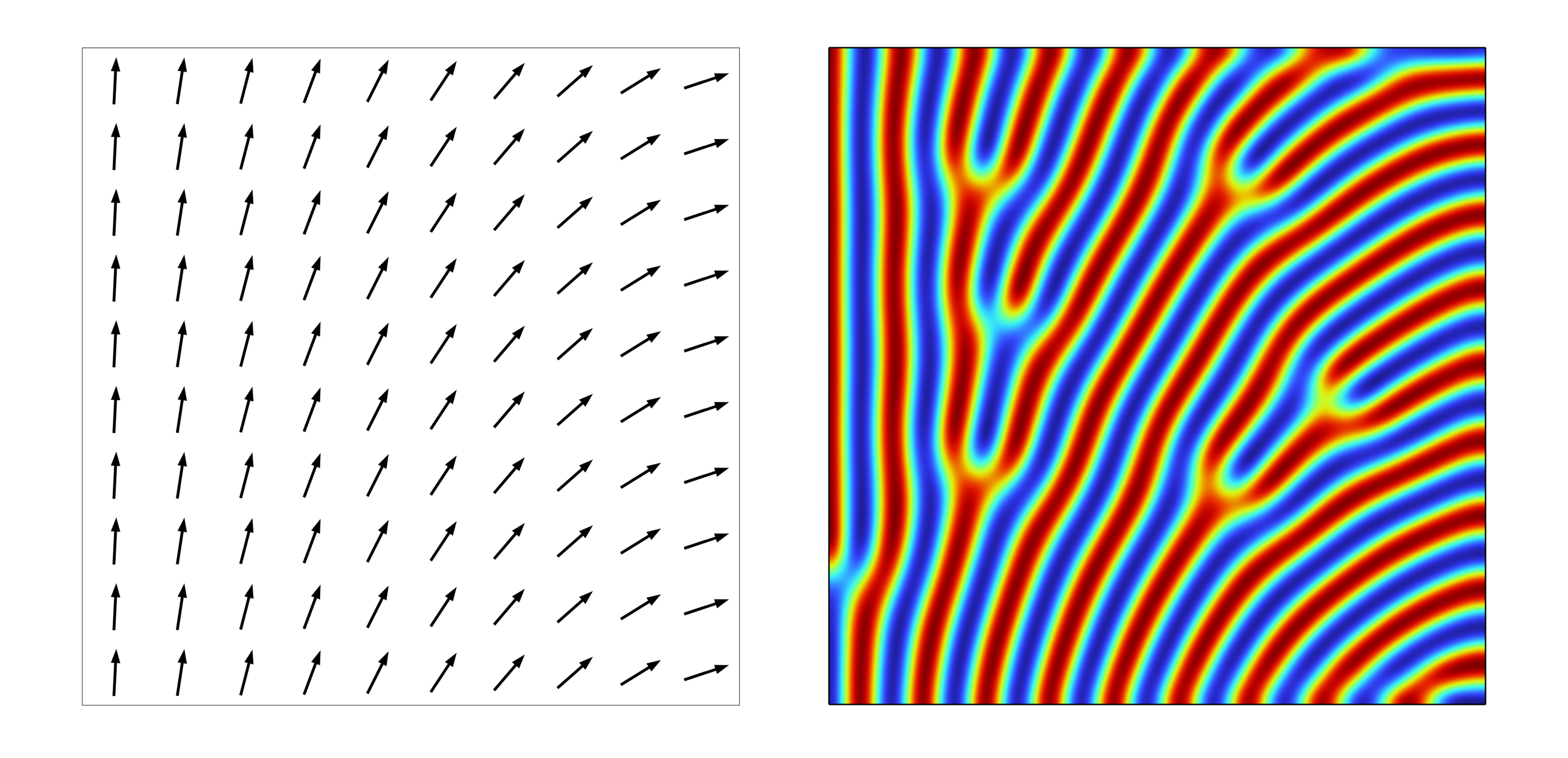
Wie konnte das TRINA-Team seine Methodik nutzen, um effizient bessere Mikrokanaldesigns zu entwickeln? Zunächst simulierten sie idealisierte Strömungsbahnen durch das effektive anisotrope poröse Material, wie links in Abbildung 6 gezeigt. Davon ausgehend extrahierten sie Werte, die das idealisierte Fluidverhalten beschrieben. Anschließend gaben sie diese Werte in eine weitere Simulation ein, die die Mikrokanalformen erzeugte, die dieses Verhalten hervorrufen (Abbildung 6, rechts). Im Wesentlichen definierten sie den Effekt, den sie mit ihren Designs erzielen wollten, bevor sie sie entwarfen. Diese Sequenz beschreibt die Umkehrung hinter dem inversen Design.
In ihrem Forschungsartikel formulierte es das TRINA-Team so:
„Durch den Verzicht auf die explizite Modellierung von Kanälen während der Optimierungsphase, die eine große Anzahl von Funktionsauswertungen erfordert, wird die Physik innerhalb eines anisotropen porösen Mediums durch eine relativ grobe Netzdiskretisierung des Designgebiets erfasst.“
„Unser COMSOL-Modell des porösen Materials hat nur zwei Materialwerte und ein sehr grobes Netz“, erklärt Zhou. „Wir implementieren einen sensitivitätsbasierten Optimierungsprozess, der auf den Navier-Stokes- und Advektions-Reaktions-Diffusions-Gleichungen basiert. Wir gehen von einer stationären, inkompressiblen und laminaren Fluidströmung durch die porösen Medien aus und davon, dass die gewünschten chemischen Reaktionen proportional zur Konzentration der Reaktanten ablaufen. Wir führen diese Simulationen durch, um eine optimale Verteilung der Strömungsrichtung des Fluids durch die Poren zu finden. Dieser Prozess liefert uns wertvolle Ergebnisse mit einer enormen Reduzierung der rechnerischen Komplexität.“
Zhou bezeichnet diesen Teil des gesamten Designprozesses als Homogenisierung. Nachdem ein Muster idealer Bahnen für das Fluid durch die Poren der Platte festgelegt wurde, ist der nächste Schritt die Dehomogenisierung. Dieser Schritt beinhaltet die gleichungsgesteuerte Definition von Mikrokanalformen, die das Fluid zwingen, diesen optimalen Bahnen zu folgen.
Maximale Strömung, maximale Reaktion oder beides
Der Schritt der Dehomogenisierung ist notwendig, so Zhou, weil „wir kein ideales poröses Material herstellen können, bei dem jede Pore individuell gestaltet ist. Wir müssen Wände und Kanäle einbauen, um das Fluid auf eine Weise durch die Poren zu leiten, die dem Ideal nahekommt. Für die Erstellung dieses Designs verwenden wir COMSOL Multiphysics®, um eine maßgeschneiderte partielle Differentialgleichung für die Mustergenerierung zu lösen. Die Software bietet uns auch Plot-Funktionen, mit denen wir die Ergebnisse visualisieren können.“
Zwei der formalen Optionen, die sich aus den TRINA-Dehomogenisierungsgleichungen ergeben, sind in Abbildung 7 und Abbildung 8 dargestellt. Wie bereits erwähnt, sind die wichtigsten Leistungsziele 1) die Verringerung des Widerstands gegen den Reaktantenfluss und 2) die Verbesserung der Reaktantenzufuhr und der Gleichmäßigkeit der Reaktion über die gesamte Platte. Diese Ziele werden in der partiellen Differentialgleichung des Modells durch bestimmende Variablen dargestellt. Indem sie diesen beiden Zielen unterschiedliche Gewichtungsfaktoren zuweisen, können Zhou und sein Team das Modell dazu bringen, verschiedene Designoptionen zu generieren. So können sie die relativen Vorteile jeder Option bewerten und Anpassungen vornehmen, um weitere Iterationen durchzuführen.
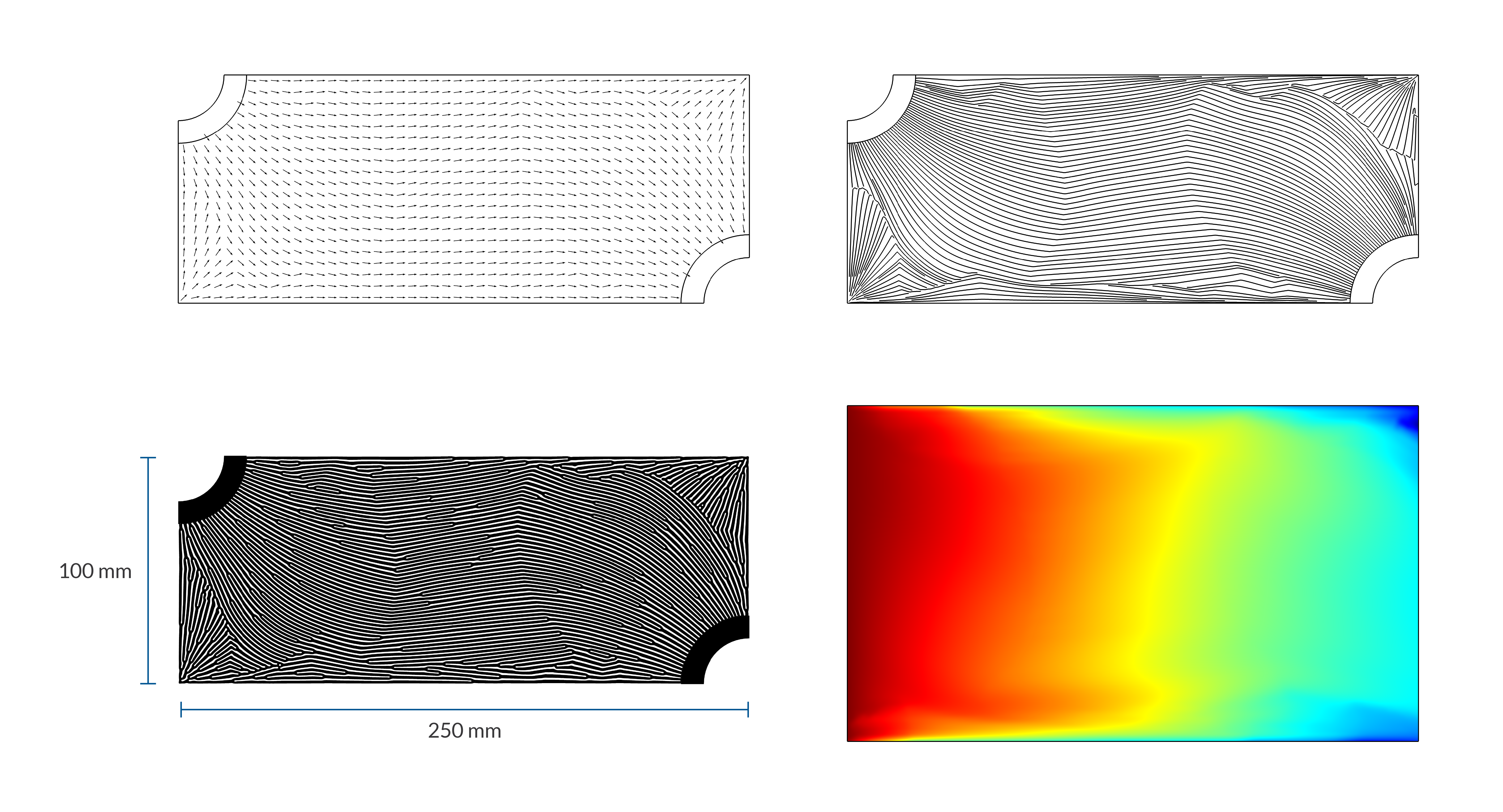
Zu dem in Abbildung 7 gezeigten Design sagt Zhou: „Wir nennen dieses Design das „Strömungsdesign“, weil es zu dem geringsten Druckabfall über die gesamte Strömungsfeldoberfläche führt. Das Modell hat Pfade generiert, die relativ parallel und gerade sind, ohne viele Verzweigungen.”
Während dieses Design das Fluid effektiv über die Platte bewegt, gelingt es ihm weniger gut, den Reaktanten gleichmäßig durch die poröse Schicht zu verteilen. Die Simulation zeigt eine geringere Reaktantenkonzentration (grün und blau in Abbildung 7 unten rechts) auf der Auslassseite des Designs, was die Gleichmäßigkeit der Reaktion und die daraus resultierende Leistungsabgabe der Brennstoffzelle einschränken kann.
Was wäre, wenn die Gewichtungsfaktoren in der maßgeblichen Gleichung so angepasst würden, dass die Gleichmäßigkeit der Reaktion Vorrang vor der Strömung hätte? Das Modell würde dann ein Design wie das in Abbildung 8 gezeigte erzeugen, das Zhou als „Reaktionsdesign“ bezeichnet. Hohe Reaktantenkonzentrationen (rot und orange in der Abbildung unten rechts) überwiegen jetzt, was bedeutet, dass ein größerer Teil der verfügbaren Reaktanten umgesetzt wird. Die verschlungenen Formen der Mikrokanäle im „Reaktionsdesign“ könnten Biologiestudenten bekannt vorkommen.

„Die meisten kommerziellen Mikroreaktoren würden ein Design verwenden, das dem Strömungsdesign ähnelt“, sagt Zhou. Aber natürlich vorkommende Systeme, die fluide Reaktanten verteilen - wie Blätter, Lungen und Blutgefäße - ähneln eher den Formen in Abbildung 8.
„Ingenieure würden vielleicht gerade Kanäle ohne Seitenverzweigungen bevorzugen, aber die Natur wählt das Reaktionsdesign“, sagt Zhou. In der Forschungsarbeit des TRINA-Teams wird darauf hingewiesen, dass zwar schon früher mit natürlich aussehenden, fraktalen oder hierarchischen Formen experimentiert wurde, die a priori für Strömungsfeldkanäle ausgewählt wurden, aber „dies ist das erste Mal, dass solche großflächigen, verzweigten Strömungsfelder mit einem inversen Designansatz entdeckt wurden, ohne dass von vorgegebenen Layouts ausgegangen wurde.“
Die Zukunft erschaffen anstatt sie vorherzusagen
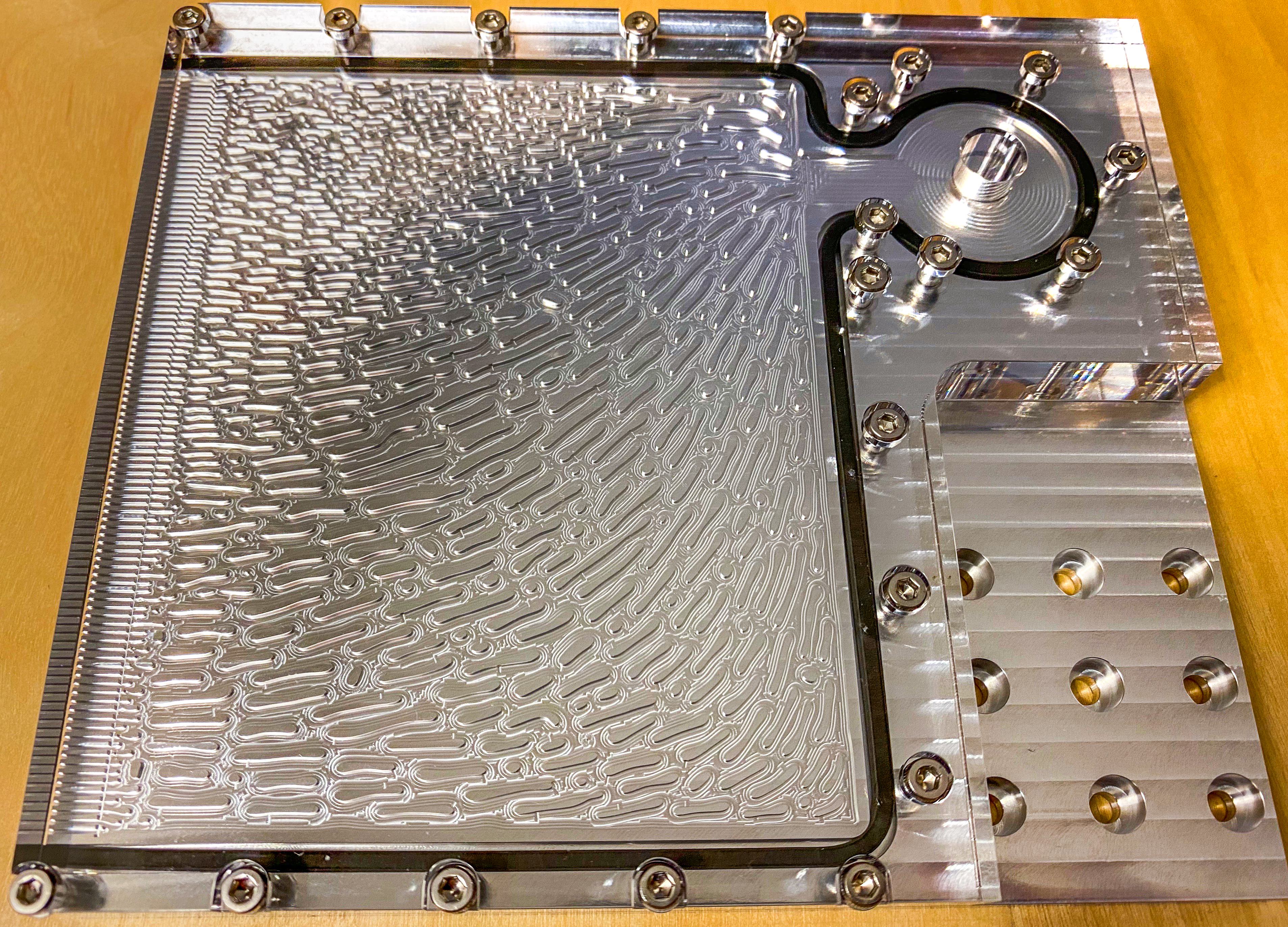
Neben dem oben gezeigten Vergleich zwischen Strömung und Reaktion erstellte TRINA zwei weitere Entwürfe (nicht abgebildet), die Eigenschaften der in den Abbildungen 7 und 8 gezeigten Designs kombinierten. Es ist bezeichnend, dass jede der vier Iterationen von TRINA die konventionellen Basisdesigns in den wichtigsten Leistungskennzahlen übertraf. Ein weiteres Design, das vom TRINA-Team hergestellt und experimentell getestet wurde (Ref. 4), ist in Abbildung 9 dargestellt.
Was ist also das ideale Design für eine Strömungsfeldplatte? Das gibt es genauso wenig wie es eine einzige ideale Technologie für die Ablösung von benzinbetriebenen Autos gibt. „Aus unserer Sicht sind wir erfolgreich, wenn wir unseren Ingenieuren mehrere gute Optionen anbieten können,“ sagt Zhou.
TRINA ist Teil eines großen Netzwerks von Toyota F&E-Teams, die sich um die Verwirklichung einer möglichen Wasserstoffgesellschaft bemühen. Das Unternehmen hat die Reichweite und Leistung der wasserstoffbetriebenen Autos, die es Mirai nennt, weiter verbessert. Mirai ist ein japanisches Wort und bedeutet „die Zukunft“ oder wörtlich „noch nicht eingetroffen“. Vielleicht werden wir in einer Welt, die noch nicht eingetroffen ist, in smogfreien Städten leben, die mit einer Infrastruktur für die Verteilung von Wasserstoff und mit Brennstoffzellen betriebenen Autos, Lastwagen, Zügen und Gebäuden ausgestattet sind. Auch wenn wir nicht sicher sein können, dieses Ziel zu erreichen, können wir, die wir in der heutigen Erdölgesellschaft leben, uns dennoch von Toyotas Weg zu Mirai inspirieren lassen.
Yuqing Zhou teilt einen Rat, der ihn und seine Kollegen leitet: „Unser leitender Wissenschaftler hat gesagt: Wir müssen aufhören zu versuchen, die Zukunft vorherzusagen, und einfach daran arbeiten, sie zu erschaffen.“
Referenzen
- L. Printz, "Toyota Remains the World's Largest Automaker," The Detroit Bureau, 28 Jan. 2022; https://www.thedetroitbureau.com/2022/01/toyota-remains-the-worlds-largest-automaker/
- Y. Zhou et al., "Inverse Design of Microreactor Flow Fields through Anisotropic Porous Media Optimization and Dehomogenization," Chemical Engineering Journal, vol. 435, pt. 2, May 2022; https://doi.org/10.1016/j.cej.2022.134587
- "Akio Toyoda Fields Questions on Carbon Neutrality from U.S. Reporters," Toyota Times, 22 Nov. 2022; https://toyotatimes.jp/en/toyota_news/1011.html
- E. Dede et al., "Measurement of Low Reynolds Number Flow Emanating from a Turing Pattern Microchannel Array Using a Modified Bernoulli Equation Technique," Experimental Thermal and Fluid Science, vol. 139, November 2022; https://doi.org/10.1016/j.expthermflusci.2022.110722
Toyota Mirai ist eine eingetragene Marke der Toyota Motor Corporation.