Heat Transfer in Adsorption Heat Exchangers between Pellets and Fins
Adsorption heat exchangers (AdHXs) are important components in adsorption heat pumps and chillers, a primary energy efficient source of heating and cooling. Due to availability and established inexpensive manufacturing fin-and-tube type heat exchangers with beds of adsorption pellets in the finned space are widely used in state of the art products (Figure 1). For design and optimization the adsorption cycle needs to be modeled dynamically, i.e. the governing transport phenomena in AdHXs need to be quantified as functions of design parameters like geometry or material properties.
A systematic modelling approach starts with analyzing single resistances apart in detailed PDE-models (1,2). The different detailed results are then reduced where possible and finally combined with a material model to a simplified dynamic model. Preferably this is a lumped parameter model (ODE-model) allowing variations and evaluations in system simulations on larger time scales. The heat transfer between fin surface and adsorbent pellet distinguishes AdHX from other applications of fin-and-tube heat exchangers and is not described in standard text books, but only few publications (3). In this work it is analysed for the case of a mono layer of pellets on each fin surface.
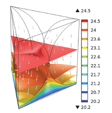
The analysis is based on a 3D stationary solid heat transfer model implemented in COMSOL Multiphysics®. The geometry shown in Figure 1 consists of a symmetrical section of a monolayer of a dense sphere packing with a gas and three pellet domains. As density of the gas and characteristic lengths are small, heat transfer in the gas domain is assumed to be dominated by conduction. An imperfect contact between pellet and wall due to surface roughness is modeled by a gap between pellet and wall. Low gas density and short conduction paths might also lead to a violation of continuum thermal conduction. This is reflected by the models range of validity.
The heat exchanger fin is modeled by applying a constant temperature BC to the “wall” face of the gas domain. Adsorption in the pellet is modeled by a homogeneous volumetric heat source in the pellet domain.
The model has been evaluated for generic material combinations with a variation of pellet size (0.1–5 mm), pellet roughness (10–500 µm) and thermal conductivity of gas (0.01–0.03 W/mK) and pellet (0.1–0.3 W/mK). From the results the mean wall heat flux, the mean pellet temperature and thus the effective heat transfer coefficient were derived.
For the parameter range considered, the resulting effective heat transfer coefficient varies between 20 and 800 W/mK. Its dependency of the varied parameters is confusing. Therefore the results have been reduced to a single correlation of the three dimensionless quantities Nusselt-number, specific roughness and ratio of thermal conductivities in the form Nu = f(ϵ, r_λ) (Figure 3). A curve-fitted Nu-correlation is presented that represents the simulation results of the whole parameter space with acceptable accuracy.
It has been shown that the effective heat transfer into a mono layer pellet bed is highly dependent on pellet size and roughness. For the common configuration of silica gel or zeolite pellets with water vapor the Nusselt-number is 5 to 8, dependent on pellet roughness (the smoother the better) but independent of pellet size. The general description of the effective heat transfer coefficient in form of a Nusselt-correlation allows for variations of geometry and material properties in simplified models without necessity of running laborious 3D heat transfer simulations. For further research an extension of the model to non-continuum thermal conduction, forced convection and multilayer beds is desirable.
Herunterladen
- laurenz_presentation.pdf - 0.64MB
- laurenz_paper.pdf - 0.75MB
- laurenz_abstract.pdf - 1.29MB