Particle Tracing for Electric and Thermal Exposure in a Continuous-Flow PEF Treatment Chamber
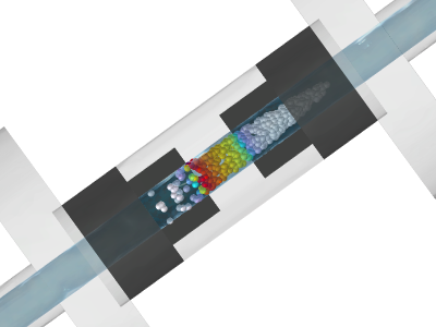
Pulsed electric field (PEF) treatment is based on electroporation, in which short, high-intensity electric pulses transiently increase cell membrane permeability [1]. PEF is used in food processing and biotechnology for applications including microbial inactivation and enhanced extraction of intracellular compounds. Although the electroporation mechanism is nonthermal, the pulses generate ohmic heating that may affect product quality. Treatment outcomes therefore depend on both electric-field and thermal exposure. In a continuous-flow PEF chamber, the product is exposed to electrical pulses while flowing between electrodes. Treatment is conventionally characterized using mean residence time, number of pulses, treatment time, and specific energy input [2]. However, cells follow different trajectories and may therefore experience different electric-field and thermal exposures. This study presents a particle-level modeling framework for quantifying these trajectory-dependent exposures and their population distributions. A previously validated 3D model of a colinear continuous-flow chamber was implemented in COMSOL Multiphysics® [3]. A stationary Laminar Flow study was followed by a time-dependent electrothermal study coupling the Electric Currents and Heat Transfer in Solids and Fluids interfaces. Two approaches were used: a pulse-resolved method using a time-dependent voltage boundary condition and Events, and a duty-cycle approximation using constant electric potential and time-averaged Joule heating. After the electrothermal solution reached a periodic steady state, a Particle Tracing for Fluid Flow study calculated trajectories from the stationary velocity field over the final 50 s of the simulation. LiveLink™ for MATLAB® synchronized the study with the exact stored electrothermal time points and extracted electric-field and temperature histories for exposure analysis (Figure 1). 10,000 massless particles were released with velocity-weighted probability, ensuring that the resulting exposure distributions represented continuous-flow treatment. For each particle, the maximum temperature and cumulative exposure time above 5 kV/cm were calculated. Five representative trajectories spanning the volumetric-flow distribution were selected to illustrate electric-field and temperature exposure. Two protocols with equal nominal treatment time and specific energy input were compared at an applied voltage of 14 kV and a flow rate of 2 L/h: 100 µs pulses at 1 Hz and 10 µs pulses at 10 Hz. Particle tracing reproduced the analytical velocity and residence-time distributions for fully developed laminar pipe flow (Figure 2). About 75% of particles had residence times below the mean, showing that mean-based parameters do not reflect exposure for most particles. Representative trajectories showed that slower near-wall particles received more pulses and were exposed to higher temperatures than central particles (Figure 3). These differences produced broad distributions of maximum temperature and exposure time above 5 kV/cm (Figure 4), with many particles in both protocols accumulating exposure times substantially below the nominal 200 µs treatment time. The duty-cycle approximation agreed with the pulse-resolved model for the 10 µs, 10 Hz protocol but missed the discrete exposure distribution and higher-temperature tail for the 100 µs, 1 Hz protocol. The framework converts field solutions into particle-specific treatment histories and population exposure distributions, enabling direct assessment of treatment homogeneity and supporting optimization of chamber geometry, flow conditions, and pulse protocols to reduce under- and overexposure.
Herunterladen
- 15 - Peter Lombergar.pdf - 1.72MB