
Simulating the interaction of a multibody mechanism with surrounding fluid is often an interesting but challenging task for many design engineers. The COMSOL® software provides an easy solution for this problem with the Fluid-Structure Interaction, Pair multiphysics coupling, available as of version 5.4. In this blog post, we discuss the Fluid-Structure Interaction, Pair multiphysics coupling in detail along with an interesting example.
What Is Fluid-Structure Interaction?
Any multiphysics problem where a solid and fluid are coupled to influence the behavior of each other falls under the class of fluid-structure interaction (FSI). Generally, when a solid object is placed in the path of a fluid, the fluid applies pressure and viscous forces on the boundaries of the structure, leading to its deformation. The deformed structure, in turn, acts as a moving wall boundary for the fluid and changes the flow field. Depending on the type of interaction, it can be either unidirectional (a one-way coupling) or bidirectional (a two-way coupling). The main objective of FSI analysis is the computation of stress and strain in the structure as well as the velocity and pressure field of the fluid flow.
FSI in a multibody assembly.
While most of the conventional, analytical, or numerical methods for solving FSI problems demand intense efforts, the COMSOL Multiphysics® software simplifies the work with its inherent ability to easily couple different physics interfaces. For modeling FSI problems, COMSOL Multiphysics provides a set of predefined multiphysics interfaces that can couple different structural mechanics interfaces (such as Solid Mechanics, Multibody Dynamics, Shell, and Membrane) with different fluid flow interfaces (either single-phase or multiphase flow).
In addition to the respective structural mechanics and fluid flow interfaces, each of these predefined FSI interfaces also contains a multiphysics coupling. The fluid flow problem is defined on a moving mesh, called the spatial frame, while the solid mechanics problem is defined on the material frame. There is an additional set of equations that keeps track of the moving mesh using the deformation of the solid structure as boundary conditions. This method is called the arbitrary Lagrangian-Eulerian (ALE) method. The multiphysics coupling node provides the coupling between the fluid and the solid structure by accounting for the moving mesh and the deformation of the material as well as for transferring fluid forces to the structure.
Different FSI Scenarios
Using COMSOL Multiphysics, you can simulate FSI in systems exhibiting different types of dynamics. For example, some FSI systems may show large relative motion between parts, while in some other cases, the relative motion between parts may not be significant. To address these different modeling scenarios, there are two different FSI multiphysics coupling features:
- Fluid-Structure Interaction
- Fluid-Structure Interaction, Pair
The Fluid-Structure Interaction feature is used in most of the general cases of FSI to model systems with relatively small motion between parts. In such cases, the fluid and solid physics interfaces in the model may share common boundaries. This is achieved in COMSOL Multiphysics by setting up the model geometry as a union of all geometry parts, which is the default behavior of the geometry sequence in COMSOL Multiphysics. You can find uses of this feature in various example models, including Vibrating Beam in Fluid Flow, Ball Check Valve, and Micropump Mechanism.
Now, imagine an instance where you want to model the interaction of a multibody mechanism with a surrounding fluid, where individual parts may slide or move to a very large extent relative to each other. Some common examples could be a swimming mechanism or the flow of air around a wind turbine blade or a helicopter blade. The Fluid-Structure Interaction, Pair feature, available in version 5.4, easily takes care of this scenario. In such cases, the system geometry would have to be in an assembly state in order to cope with the large relative movements at the assembly boundaries. Force contributions are then specified on respective sides of the boundary pairs created between fluid and multibody boundaries.
The table below summarizes the two FSI features.
Geometry Sequence ModeUnionAssembly
| Fluid-Structure Interaction | Fluid Structure Interaction, Pair | |
|---|---|---|
| Interaction Contribution | Applied through common boundaries between the solid and fluid domains | Applied through boundary pairs with the solid domain on one side and fluid domain on the other side |
| Mesh Deformation | Automatically transfers the full structural displacement field on all common boundaries | Needs to manually transfer the full or only normal component of the structural displacement field on the appropriate fluid boundaries |
How to Model FSI in Multibody Mechanisms
In this section, we will demonstrate how you can add the Fluid-Structure Interaction, Pair feature to your model either through a predefined multiphysics interface or separately.
As mentioned earlier, COMSOL Multiphysics has different predefined FSI interfaces, with solid mechanics and fluid flow interfaces added in. Additionally, one of the two multiphysics couplings is also built in. Of those multiphysics interfaces, the Fluid-Multibody Interaction, Assembly interface, which is mainly designed for the modeling of multibody mechanisms interacting with surrounding flow fields, has the built-in Fluid-Structure Interaction, Pair feature.
You can add the Fluid-Multibody Interaction, Assembly interface to your model from the list of Fluid-Structure Interaction interfaces in the Fluid Flow node in the Model Wizard, as shown in the figure below. This adds a predefined Laminar Flow interface, Multibody Dynamics interface, and multiphysics coupling node with the Fluid-Structure Interaction, Pair feature. It also contains a Moving Mesh node with a Deforming Domain subnode. If you have not selected this predefined interface at the beginning, you can still couple your multibody dynamics and fluid flow physics interfaces during the course of modeling.
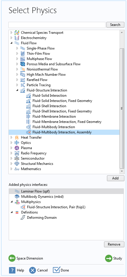
Adding the Fluid-Multibody Interaction, Assembly interface in the Model Wizard.
After adding the multiphysics interface, the Model Builder looks like the figure below. Here, the Multibody Dynamics interface is used for modeling the structural assembly of rigid or deformable solid bodies. The fluid flow can be modeled with one of the single-phase flow or multiphase flow interfaces.
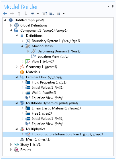
Model Builder after adding the Fluid-Multibody Interaction, Assembly interface.
As mentioned, in order to apply the Fluid-Structure Interaction, Pair multiphysics coupling, you need to have your model geometry built in an assembly state. While creating the geometry in assembly mode, there is an option available to create boundary pairs automatically between all of the boundaries that are located at the same geometrical positions, but that belong to separate parts in an assembly. As shown in the figure below, this is possible through the Create pairs check box in the Settings window, which creates identity pairs between pairs of adjacent boundaries. All of these pairs are listed in the Pair Selection section of the Fluid-Structure Interaction, Pair feature. From this list, ideally, you need to select only those pairs that are relevant and between solid and fluid domains, however you can select all of the pairs, and this feature automatically ignores the pairs that are not between solid and fluid boundaries.


Creating identity pairs and selecting them in the Fluid-Structure Interaction, Pair node.
The geometrical changes happening in the fluid domain due to its interaction with the neighboring solid domain are modeled through the arbitrary Lagrangian-Eulerian (ALE) formulation mentioned above. For that, a Deforming Domain feature is added under the Moving Mesh node. This node has an empty selection by default, but you can assign it to the fluid domain that undergoes large geometrical changes.
Different boundary conditions are available for specifying the motion of the moving mesh boundaries. Depending upon the dynamics of your mechanism, you can choose appropriate boundary conditions for the moving boundaries and transfer the relevant components of solid displacement to the spatial frame. This is possible with the help of a few built-in variables available in the coupling feature. For example, use a Prescribed Mesh Displacements boundary condition to transfer the motion of adjoining solids to the moving mesh, which sets the displacement of the mesh boundaries equal to the mapped solid boundaries of the identity pairs.
Simulating FSI in a Mechanism Submerged in Fluid
Inspired by many of the FSI systems in nature, engineers have designed a number of mechanisms for various experimental and industrial examples. The Mechanism Submerged in Fluid model (available in the Application Gallery) is one such example. It simulates the motion of a mechanism submerged in a fluid channel, vaguely resembling the swimming motion or forward motion of a microorganism with the help of the locomotive structures at the back.
The model here demonstrates the motion of a rigid body with two flexible fins in a flow channel. The fins are connected to the body through hinge joints, which permits their in-plane rotation. The motion of the mechanism is initiated by a prescribed rotation of the fins about the central body in a time-dependent manner. The fluid channel is described by the incompressible Navier-Stokes equations for the velocity field and the pressure in the spatial (i.e., deformed) moving coordinate system. The Multibody Dynamics interface is used to model the structural assembly. The geometrical changes in the fluid domain are incorporated in the model by assigning a deforming domain to the fluid part.
As for transferring the motion of the solid elements to the spatial frame, two different types of moving mesh boundary conditions are used, as shown in the figure below.
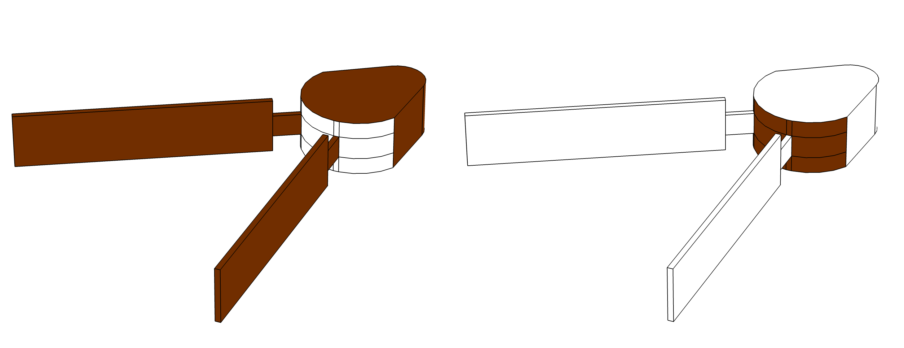
Transfer of solid motion to the moving mesh. Left: On the boundaries highlighted, all components of the solid motion are transferred to the adjacent moving mesh boundaries. Right: On the rear curved face highlighted, only the normal components of the solid motion are transferred to the moving mesh boundaries, keeping the mesh free to slide tangentially.
A Prescribed Mesh Displacement boundary condition is used to transfer solid displacements to all of the fluid boundaries except the curved faces at the back. For that, the built-in variables (fsip1.u_solid, fsip1.v_solid, and fsip1.w_solid) are used, which set the displacement of the mesh boundaries equal to the mapped solid boundaries of the identity pairs. At the back side of the solid body, the contact area between the solid and fluid boundaries continuously changes because of the rotational motion of the fins. Using a Prescribed Normal Mesh Displacement boundary condition at these boundaries, the mesh is allowed to move freely in the tangential direction and be equal to the solid normal motion in the normal direction. For that, a normal displacement variable, un_solid = fsip1.u_solid*(nX)+fsip1.v_solid*(nY)+fsip1.w_solid*(nZ), is used, as shown in the figure below.


Moving Mesh boundary conditions.
Note that the choice of different Moving Mesh boundary conditions on different boundaries largely depends on the mechanism. There is no general rule for that, and you need to set it appropriately depending upon the dynamics of the mechanism. In many common mechanisms, allowing mesh slip on the boundaries near solid-solid pairs helps to capture system dynamics accurately.
Unlike the mesh generated for the union geometry sequence, the mesh on the two sides of a pair may not be matching. As the faces of the elements and the node points are not the same, this may at times affect the accuracy, especially when the relative element sizes across the pair are very different. In cases where you want to have matching mesh on both sides of a pair, you can copy mesh from one side to other. Here, as the mechanism moves forward along the x-axis, the mesh undergoes stretching in the direction of motion. If the displacements are too large, there is a high probability that you may get a highly distorted mesh. In that case, you need to consider the option of remeshing to generate a new mesh.
Mesh in the mechanism and lower half of the fluid domain.
Visualizing the Simulation Results
The time-dependent rotational motion of the fins drives the mechanism. During the first quarter of the simulation time, they rotate equally in opposite directions. This brings the fins closer to each other, leading to the compression of the fluid between them and expansion of the fluid outside. After this, the fin rotation is kept constant. The net forward motion of the mechanism is the result of the transmission of velocity from the structure to the fluid.
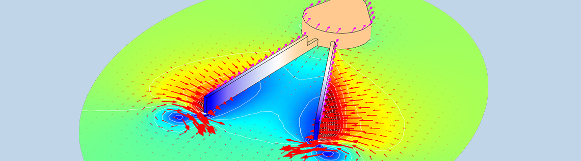
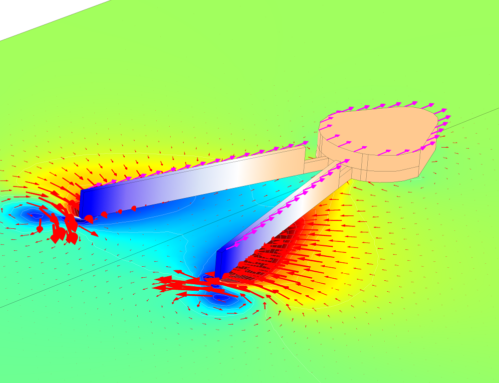
Displacement and velocity in the mechanism together with the velocity field and pressure in the fluid on the central xy-plane (left) and xz-plane (right).
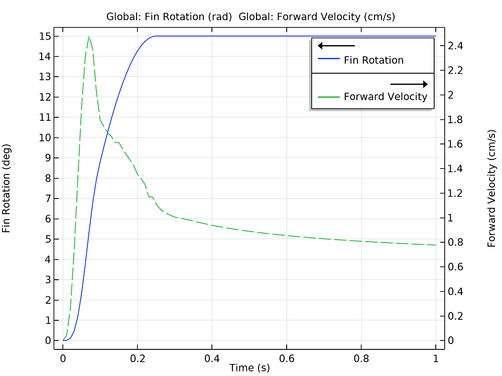
Fin rotation and forward velocity of the mechanism as a function of time.
You can further explore some of the interesting dynamics of the system for varying prescribed motion types and other sets of parameters.
Other Examples for Using the Fluid-Structure Interaction, Pair Feature
Below are some common examples where you can use the new Fluid-Structure Interaction, Pair feature to couple a multibody mechanism with a flow field and simulate the large relative motion between parts.
- Rotation of the blades for aeroelastic structures like helicopters or wind turbines
- Flapping of the wings of an aircraft or a bird while flying
- Swimming-like motion; e.g., simulating the motion of a fish in water
- Systems like a magnetorheological fluid damper with relative translational motion between fluid and solid domains
With the help of useful functionalities provided by this feature, you can address similar, or more complex, fluid-multibody interactions in a simple way.
Next Steps
To try using the Fluid-Structure Interaction, Pair multiphysics coupling, click the button. Doing so will take you to the Application Gallery, where you can download PDF documentation for the Mechanism Submerged in Fluid model and the accompanying MPH file.

Comments (12)
Huseyin Uvet
January 18, 2020Hi,
I’m looking for an example of the model which titled “Flapping of the wings of an aircraft or a bird while flying”. Can you provide this example ?
Soumya S S
January 20, 2020 COMSOL EmployeeHi Huseyin,
As mentioned in the post, these are certain scenarios where you can use Fluid-Structure Interaction, Pair feature to model the system dynamics. For all these cases, the model set up would be similar to the mechanism submerged in fluid tutorial model mentioned above. Currently we don’t have a dedicated example model in the model gallery, particularly modeling the flapping of wings. However, we can help you in setting up the model. You can send your specific question to support@comsol.com.
Best regards,
Soumya
Mike b
May 21, 2020First of all, Great tutorial!
I followed along with the model opened and understood the example much better.
A questions I had: How to choose the best mesh deformation constraint? I’m not clear why the Prescribed Mesh Displacement and the Prescribed Normal Mesh Displacement were used here. why not the Mesh Slip?
Soumya S S
May 22, 2020 COMSOL EmployeeHi Mike,
By choosing appropriate mesh deformation constraints, our aim is to transfer the motion of solid parts to moving mesh. Hence the choice of mesh constraints depends on the dynamics of each problem. In this example, all components of solid motion have to be transferred to the moving mesh for all boundaries except the curved ones. That’s the reason for choosing Prescribed Mesh Displacement boundary conditions there. For the curved boundaries, mesh is allowed to move freely in tangential direction, but the normal components of the solid motion have to be transferred to the moving mesh boundaries. Hence, we use a Prescribed Normal Mesh Displacement boundary condition, which has no constraint in tangential direction but equal to the solid normal motion in the normal direction. A Mesh Slip boundary condition can be used on the boundaries of deforming domains where the mesh can slip (that is, only move in the current tangential direction). The condition is equivalent to specifying a zero normal mesh velocity in a Prescribed Normal Mesh Velocity node.
For more information about different mesh boundary conditions, you can refer to COMSOL Multiphysics Reference Manual, Deformed Geometry and Moving Mesh chapter.
Regards,
Soumya
Muhammad Zain Ul Abideen
February 19, 2024Hello.Soumya S S
I hope this finds you well. My name is ZAIN, and I am writing to you regarding the impressive work your company has done in the field of fluid-structure interaction (FSI), particularly in the realm of sea floor energy harvesting.
I recently came across your FSI simulation on fluid and I was thoroughly impressed by the depth of your research and expertise in this area.
As part of our ongoing project in ACTIVE FLAPPING OF FLAG FROM FLUID VORTICES, we are interested in further studying and possibly incorporating aspects of your FSI simulation into our work. Therefore, we kindly request access to the COMSOL Multiphysics file and any essential materials associated with your FSI simulation on sea floor energy harvesting.
We believe that examining your simulation model and methodology would greatly benefit our research efforts and provide valuable insights into the complexities of sea floor energy harvesting.
Rest assured, any materials provided will be used solely for academic and research purposes, and we are committed to maintaining the confidentiality and integrity of your proprietary information.
If it is feasible, we would greatly appreciate your assistance in providing us with access to the requested files and materials. Additionally, please let us know if there are any specific protocols, agreements, or considerations we need to adhere to in order to obtain access.
Thank you very much for considering our request. We eagerly await your response and the opportunity to potentially collaborate or learn from your esteemed team.
Warm regards,
Soumya S S
February 19, 2024 COMSOL EmployeeHi Muhammad,
Thank you for the interest. You can find different tutorials relevant to Fluid-Structure Interaction in the Application Gallery. Below link lists some of them:
https://www.comsol.com/models?q=fluid%20structure%20interaction
If you have any specific question related to your model, we can help you in addressing that. Please send your queries to support@comsol.com.
Regards,
Soumya
云峰 付
April 26, 2021Hi, Soumya SS
I want to learn the operation process of fluid-structure interaction through some examples. How can I get those better examples?
Soumya S S
April 27, 2021 COMSOL EmployeeHi,
You can find different tutorials relevant to Fluid-Structure Interaction in the Application Gallery. The link below lists some of them:
https://www.comsol.co.in/models?q=fsi
Regards,
Soumya
chandra shekhar maurya
January 10, 2023Is soot of particles in combustion chamber possible to simulate using COMSOL?
Sen Mei
November 19, 2024Dear Soumya,
I hope this comment finds you well. I am currently using the Fluid-Structure Interaction, Pair module to simulate multi-body interactions within a water fluid and have encountered some challenges. I would greatly appreciate your guidance on the following:
1. How to set up “Moving Mesh”? I referred to the “Mechanism Submerged in Fluid” and assigned fsip1.u_solid, fsip1.v_solid, and fsip1.w_solid on the contacting fluid boundaries. However, this resulted in an error indicating “Circular variable dependency detected”.
2. When we form an assembly, should we generate “identify pair” or “contact pair”? I still feel quite confused by these.
If forming an union, the interaction between fluid and structure is automatically setup. While forming an assembly, it seems we need to set up the fluid-structure interface manually. Could you please clarify what steps are necessary for the fluid-structure interaction when forming assembly?
Your advice would be incredibly helpful in resolving these issues and advancing my simulation.
Thank you very much for your time and support.
Best regards,
Mason
Evan Sisler
December 12, 2024 COMSOL EmployeeHi Sen,
Thank you for your comment.
For questions related to your modeling, please contact our Support team.
Online Support Center: https://www.comsol.com/support
Masum Alam
April 14, 2025Hello,
I tried to do your simulation with creep flow instead of laminar flow. Technically In creep flow we used stokes equation (Omitting of inertial term from Navier Stokes equation). So, the net displacement of the swimmer from the oscillating motion should be ‘Zero’. But, when I did the simulation the net displacement in the creep flow is higher even than Laminar Flow. Can you tell me what can be the reason of that? or Should we change some other setup.