

As of version 5.4 of the COMSOL Multiphysics® software, there are features for simulating corrosion in slender structures. This significantly speeds up the total time spent when working with structures such as oil platforms. By using the boundary element method (BEM) and specialized beam elements in the Current Distribution, Boundary Elements interface, there is no longer a need for a finite element mesh to resolve the whole 3D structure, saving time for large corrosion problems consisting of slender components.
Comparing the Finite Element and Boundary Element Methods
When solving physical equations on a real, 3D geometry, numerical methods require you to discretize the model geometry. This involves breaking up the geometry into elements. At certain points in each element, the equations are solved and the relationship between the elements is described so that a finite set of equations is created.
If you choose to use a finite element method (FEM), you have to discretize the volume inside of the boundaries of your geometry. If you choose to use a boundary element method (BEM), the equation system is set up so that you only need to discretize the boundaries in the model geometry (this only works for problems that are linear in the model domain). There are then much fewer elements; however, the physical equations connect every boundary element with every other boundary element, unlike finite elements on a volume, which are connected by equations only to their neighbors. Both methods have advantages and disadvantages. This blog post discusses an example where the BEM demonstrates its efficiency.
Studying Corrosion in a Complex Structure
We wrote about the importance of corrosion management in oil platforms in a previous blog post. Such structures usually stand on a seabed with a jacket structure or float above the oil field as a floating production unit. Such jacket structures are generally quite large and complex and include a lot of pipes; steel legs; and hopefully a number of sacrificial anodes, which oxidize to protect the structure from corrosion.
When working with large structures, such as a jacket structure, there may be several hundred or even thousands of anodes that are placed quite close to the structural members. If you want to use a volumetric (3D) mesh on such structures, you will end up with a lot of surfaces and small mesh elements due to the curved surfaces and thin gaps between the anodes and the structural parts. In order to quickly assess the cathodic protection scheme of a large jacket structure, it can be useful to utilize the BEM with the edge elements provided in the Corrosion Module.
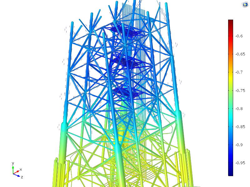
Electric potential of steel versus the Ag/AgCl electrochemical potential on a jacket structure submerged in seawater, calculated with the Current Distribution, Boundary Elements interface.
The figure above demonstrates results from a model containing more than 3000 different edges. Each edge is given a radius, and an appropriate current density is specified depending on whether it is made from steel (protected cathode) or represents a sacrificial anode. It is easy to combine several different dimensions and current densities using the selection capabilities in COMSOL Multiphysics.
By using the Current Distribution, Boundary Elements interface, you only need to create a discretization for the edges. The rest of the calculation is based on the boundary element method, which implies that no discretization of the surrounding volume is needed. Creating an edge mesh for this structure will take only a few seconds, but for a full-sized solid structure with a volumetric mesh, much more work and computational resources would be required.
Utilizing the Capabilities of the Boundary Element Method
When building a model with the Current Distribution, Boundary Elements physics interface, you need to select it from the Physics Interfaces selection list under the Electrochemistry branch.
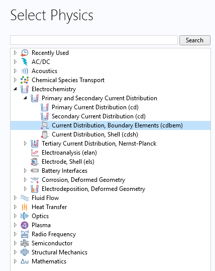
A screenshot showing the Select Physics window, with access to the Corrosion Module.
Once you have built your geometry consisting of edges, you can assign the Edge Electrode feature to input the electrode radius and electrode reaction parameters.
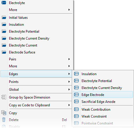
Use the Edge Electrode feature to specify the radius and electrode reaction parameters of the edge object.
By specifying the edge radius, you can also specify that it should compensate for the tube volume in the electrolyte. In turn, the edges are implemented as edge sources in an infinite electrolyte. However, if there are many edges or tubes and they are close together, they will reduce the effective conductivity of the electrolyte. Thus, if you check the box for compensation for the tube volume, each tube is treated as a solid tube at the cost of two more degrees of freedom at each element.

Compensation for tube volume, which displaces the electrolyte, may be enabled by the check box in the Settings window.
You can now define the electrode reaction as usual for anodes and cathodes and solve the model.
One of the default plots that appears after solving includes a Line plot along the edges, where the thickness of the tube is taken from the specified tube radius in the physics interface.

The potential on the edges with a tube plot, showing the virtual dimensions of the tubes.
In this blog post, we have shown a way to handle large, slender structures with the Current Distribution, Boundary Elements interface. By utilizing the BEM and specialized elements, we are able to reduce the time spent on meshing and model setup.
Enhance Your Corrosion Simulation Processes
Take a closer look at the Corrosion Module to learn more about the capabilities of COMSOL Multiphysics for cathodic protection and corrosion simulation:
Editor’s note: This blog post was updated on 12/12/18 to include information about new features available as of version 5.4 of COMSOL Multiphysics.

Comments (4)
EH Ooi
February 19, 2016May I know if the BEM feature is available only for the Electrochemistry Module?
Thank you.
Bertil Nistad
February 19, 2016The Current distribution on edges, BEM interface is only available in the electrochemistry products. (Batteries and Fuel Cells-, Corrosion-, and Electrochemistry Module)
Let me know if you have any additional questions.
Best regards
Bertil
Djedjiga BOUKHLEF
March 30, 2017I need to distance training for simulation of the cathodic protection for the buried pipes by the methode of protection by galvanic anode.
Cordially.
Caty Fairclough
April 13, 2017Hi,
Thanks for your comment!
For questions related to your modeling, please contact our support team.
Online support center: https://www.comsol.com/support
Email: support@comsol.com
Best,
Caty