Die Verwendung des Fensters Graphics und der Graphics-Symbolleiste in der COMSOL Multiphysics® Software ist einfach und unkompliziert. Wenn Sie die Mechanik und einige anspruchsvollere Techniken erlernt haben, können Sie mithilfe der Steuerung der Kamera und der Blickwinkel qualitativ hochwertige ästhetische und informative Visualisierungen erstellen.
Anmerkung des Herausgebers: Die ursprüngliche Version dieses Beitrags wurde von Lexi Carver geschrieben und am 19. März 2014 veröffentlicht. Er wurde inzwischen aktualisiert, um neue Visualisierungsfunktionen zu berücksichtigen.
Der Knoten View mit allem, was Sie brauchen
Es gibt viele Möglichkeiten, die Ansicht der Geometrie direkt im Fenster Graphics durch verschiedene Mausklicks und -bewegungen sowie durch die Schaltflächen in der Graphics-Symbolleiste zu verändern. Diese Ansichtsänderungen werden alle im Knoten View angezeigt. Es gibt allgemeine Ansichts- und Beleuchtungsoptionen, visuelle Effekte für eine realistische Schattierung sowie Umgebungs-, Transparenz- und Ausschnittseinstellungen.

Der Knoten View im Fenster des Model Builder ist ausgewählt und einige der Ansichtseinstellungen werden gezeigt, einschließlich des Kontrollkästchens Ambient Occlusion, das dem Modell Schattierungen hinzufügt. Das Fenster Graphics zeigt die Ergebnisse eines Modells zur Topologieoptimierung einer Drohne.
Licht, Kamera, Action
Es gibt viele Möglichkeiten, die Kamera zu steuern, um interessantere und informativere Ansichten zu erhalten. Vielleicht möchten Sie auf eine kleine interessante Stelle in einem größeren Modell zoomen, während Sie das gesamte Modell im Blick behalten? Oder Sie haben ein Modell, das ein hohes Seitenverhältnis aufweist? In diesen Fällen können Sie die Kamera so einstellen, dass die wichtigen Teile des Modells gut dargestellt werden.
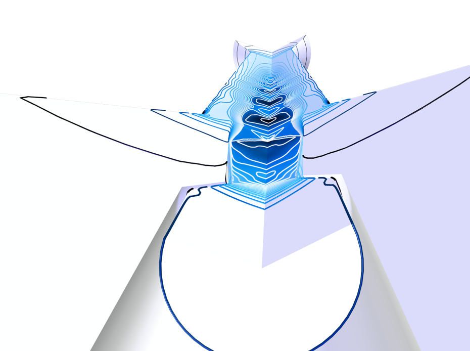
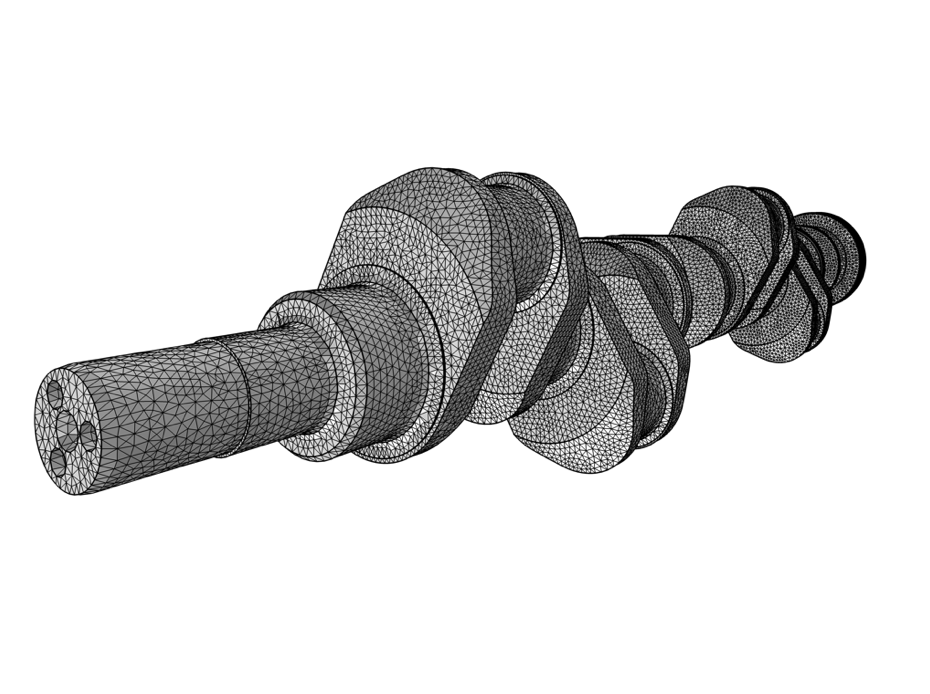
Ein Überschall-Ejektor, bei dem der Einlass im Vordergrund von Interesse ist und der Auslass im Hintergrund sichtbar bleibt (links). Das Netz einer Kurbelwelle, wobei die Netzelemente im Vordergrund zu sehen sind, aber immer noch das gesamte Modell enthalten ist (rechts).
Jeder gute Fotograf (ob Amateur oder Profi) weiß, dass die Beleuchtung für ein gut entwickeltes Bild essentiell ist. Bei der Arbeit mit COMSOL Multiphysics ist dies nicht unbedingt der Fall – die Standard-Beleuchtungseinstellungen sind normalerweise ausreichend. In der richtigen Situation kann die Beleuchtung jedoch sehr hilfreich sein, um ein Modell in Szene zu setzen. Betrachten Sie zum Beispiel dieses Modell eines Halloween-Kürbisses. Mithilfe verschiedener Beleuchtungsfeatures in der Software können wir das charakteristische gelbe Leuchten erschaffen, das eine Kerze im Inneren eines geschnitzten Kürbisses erzeugt.

Zusätzliche gelbe Punktlichter im Inneren des Kürbisses erzeugen das gelbe Leuchten und das Feature Ambient Occlusion fügt zusätzliche Schatten hinzu.
Nun werden Sie vielleicht denken: Das ist ja alles schön und gut, aber vielleicht könnten wir Ergebnisse sehen, die die tatsächliche Physik zeigen. Das folgende Modell nutzt die neuen Funktionen des Heat Transfer Module, die ab Version 6.0 zur Verfügung stehen, um die Strahlung von Oberfläche zu Oberfläche in einem von einem Ofen beheizten Raum zu simulieren. Die Wärme strahlt auf die umgebenden Oberflächen ab und wird durch Konduktion in den Möbeln verteilt. Zur besseren Visualisierung des Strahlungswärmeflusses auf den Oberflächen des Modells wurden zusätzliche Beleuchtungsfunktionen verwendet. Sowohl die Beleuchtungs- als auch die Kamerafunktionalität werden ausführlicher in dem Artikel “Using the Graphics Window” in unserem Learning Center erläutert.
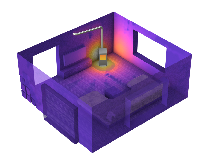
Strahlungswärmefluss durch Oberflächen in einem von einem Ofen beheizten Raum.
Wie unter einer Tarnkappe: Ausblenden von Elementen
Es wurde bereits erörtert, wie Sie den Knoten View modifizieren können, um interessante Stellen in Ihrem Modell (und den Simulationsergebnissen) hervorzuheben. Ein weiterer nützlicher Aspekt des Knotens View ist die Möglichkeit, bestimmte geometrische Elemente sowohl im Preprocessing als auch im Postprocessing auszublenden. Auch hier handelt es sich um ein Werkzeug, auf das direkt über die Graphics-Symbolleiste zugegriffen werden kann, aber die Ergebnisse der Anwendung dieses Werkzeugs werden über den Knoten View aufgerufen. Das Ausblenden von Elementen ist eine Technik, die in den meisten Simulationen verwendet wird, da es oft Wände gibt, die den Blick auf die wichtigen Ergebnisse versperren. Im Folgenden finden Sie drei Beispiele, bei denen die Ergebnisse nicht sichtbar wären, wenn wir bestimmte Teile, die nicht von Interesse sind, nicht ausblenden würden. In dem Artikel “How to Select Geometry” in unserem Learning Center erfahren Sie, wie Sie die Features zum Ausblenden verwenden können.
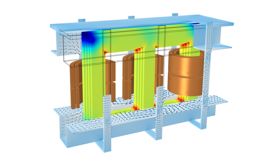 Verlustverteilung in der Verkleidung eines Leistungstransformators, von dem Teile der Verkleidung und die Hälfte von zwei Spulen ausgeblendet sind, um den Kern sichtbar zu machen.
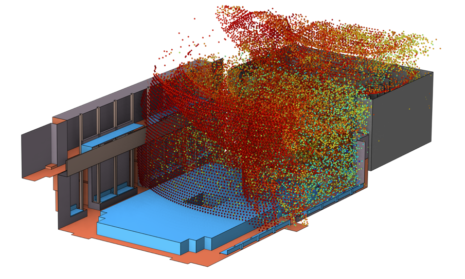 Eine Strahlenakustik-Simulation wird in einem Modell eines Kammermusiksaals durchgeführt. Die Decke, die Vorderwand und die nahe gelegene Wand sind ausgeblendet, um die Ergebnisse zu sehen.
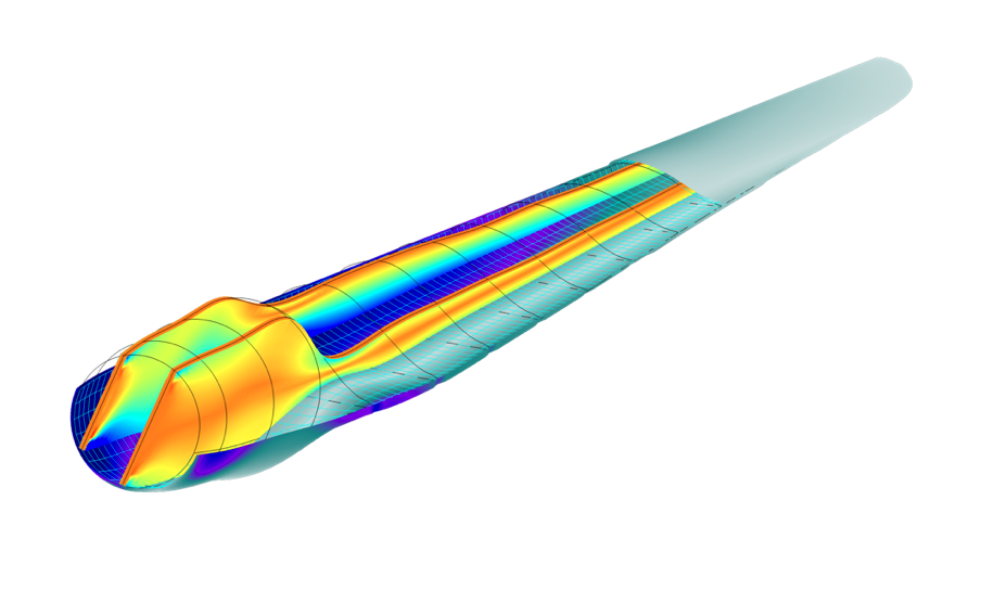 Die Verteilung der Von-Mises-Spannung in der Hülle (teilweise ausgeblendet) und im Holm eines Rotorblatts aus Verbundwerkstoff für Windkraftanlagen.


Schlussbemerkung und nächste Schritte
Wenn Sie wissen möchten, wie Sie die in diesem Blog-Beitrag besprochenen Features und weitere Funktionen der Benutzeroberfläche nutzen können, schauen Sie sich unseren Kurs zur Navigation in der Benutzeroberfläche von COMSOL Multiphysics an.

Kommentare (0)