Design Module Updates
For users of the Design Module, COMSOL Multiphysics® version 6.0 brings user interface improvements, a new Projection feature, and updated CAD file import to support the most recent CAD file versions. Learn more about these updates below.
User Interface Improvements
The buttons for adding constraints and dimensions, which you can find on the Sketch toolbar, are now sticky, so that you can add constraints and dimensions of the same kind much faster than before, without having to click the button again. Previously, only the smart Constraint and Dimension buttons were sticky. When a constraint or dimension button is active, the mouse cursor is decorated with the icon for the constraint or dimension to indicate which button is selected.
Several Equal Distance constraints are added to this sketch, which is part of a geometry sequence for creating the geometry of a permanent magnet motor. After the last equal distance constraint is added, the constraint is deactivated using the right-click contextual menu. Finally, the 2D sketch is revolved to create the 3D objects.
Projection Feature
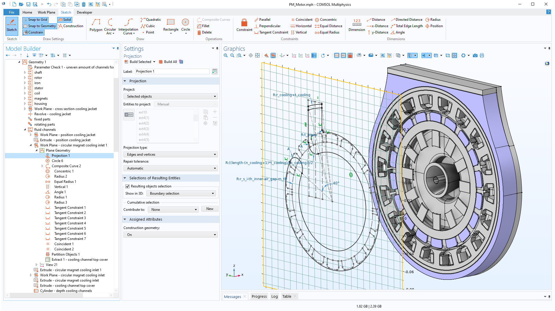
The new Projection feature, found under the Geometry tab in 2D or the Work Plane tab for work planes in 3D, can be used to project 3D objects and entities, such as faces, edges, and vertices, to work planes and 2D geometries. You can leverage the curve object that results from the projection in further geometry operations, for example, as a construction object that helps with creating other geometry objects, or to convert it into a solid object for setting up a simulation.
Improved Visualization for Detect Interferences Tool
The Detect Interferences tool has been improved to better present and visualize the interferences between geometry objects. You can now use the Group by object check box to sort the detected interferences by object. Previously, the list was sorted by the type of interference. As you select an interference from the list, the new default is to visualize only the objects that take part in the interference in the Graphics window; the other objects are hidden automatically. Other options for visualization are also available, for example, to show only the interfering faces.
The Detect Interferences tool is used here to detect and visualize the intersections and touches between the imported geometry objects of a high-voltage circuit breaker chamber.
Updated CAD File Import and Export
The CAD file import and export functionality has been extended to support the most recent versions of the supported file formats. To see a current list of supported CAD file formats, please refer to the Read from File, CAD and Write to File sections on the CAD specification chart.