Neuerungen im Bereich Geometrie
COMSOL Multiphysics® Version 6.4 bietet die Möglichkeit, Begrenzungsrahmen, Kugeln und Zylinder zu erstellen, sowie schnellere Boolesche Operationen und eine verbesserte Leistung der Geometriebereinigung. Weitere Informationen zu diesen Updates finden Sie unten.
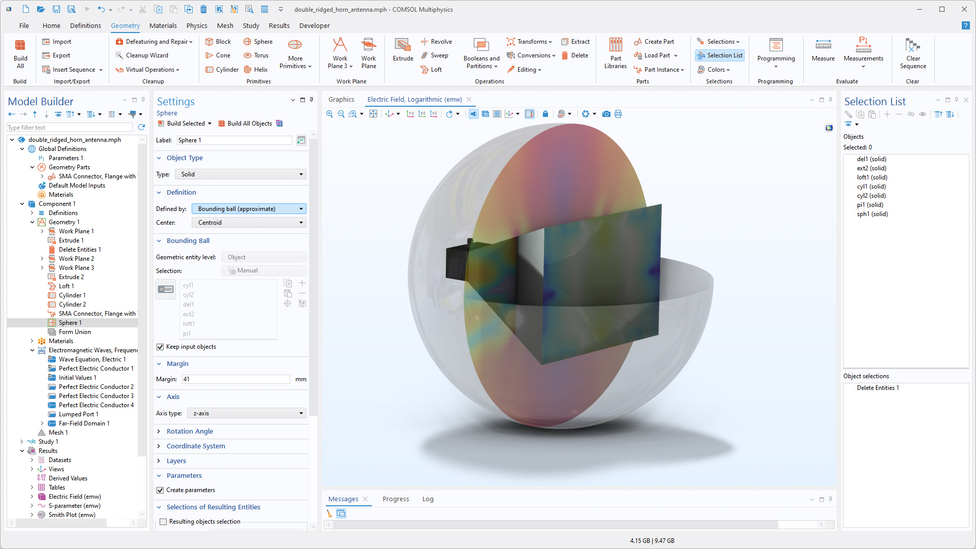
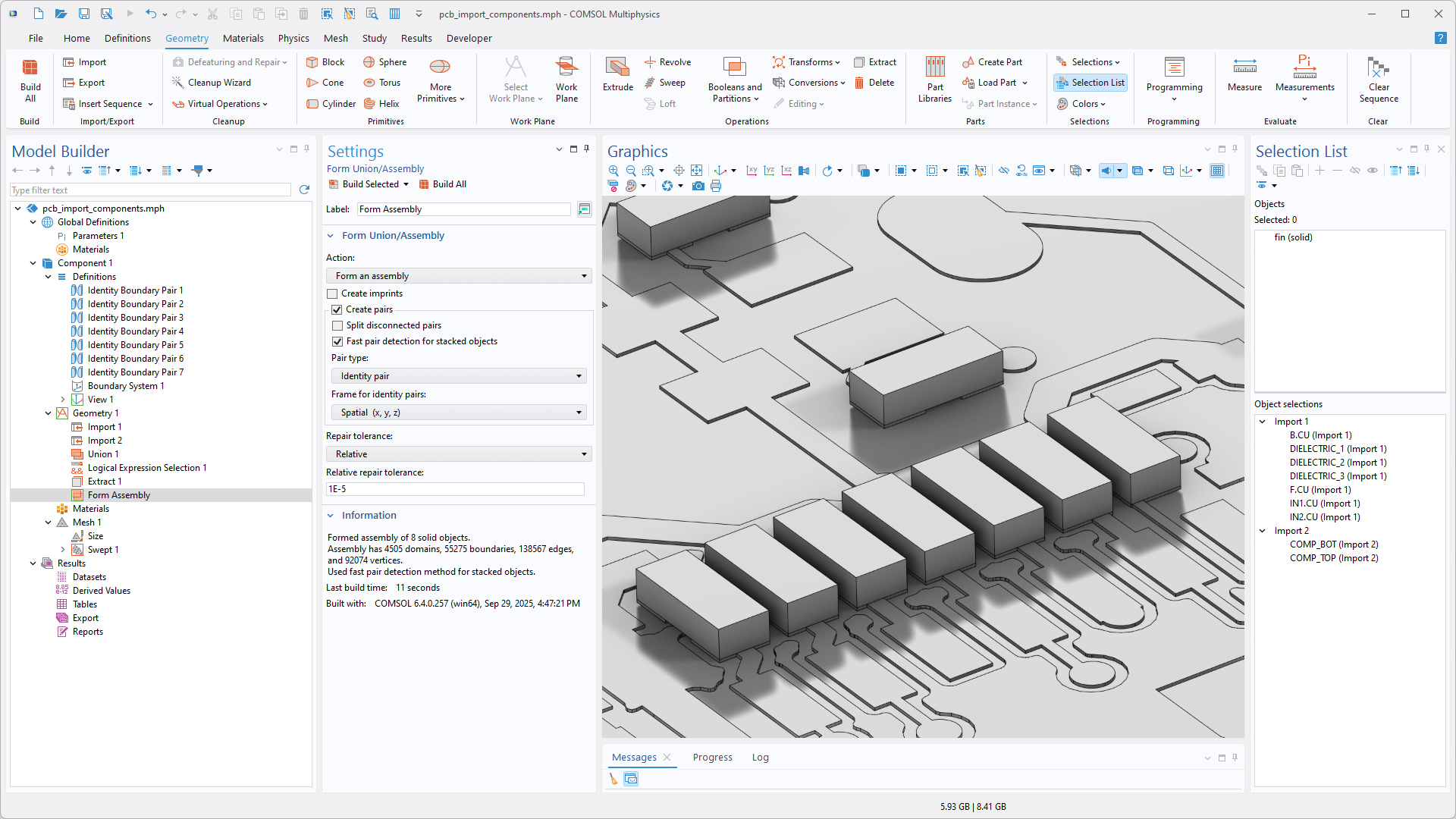
Erstellung von Begrenzungen
Beim Erstellen eines Fluid-Volumens um eine Geometrie herum oder beim Vereinfachen einer Geometrie durch Ersetzen eines sehr detaillierten Teils durch eine generische Form ist es nun möglich, eine begrenzende Box, eine begrenzende Kugel oder einen begrenzenden Zylinder mit den Grundformen Block, Sphere, Cylinder, Rectangle, und Circle zu erstellen. Die Größe des Abstands zwischen der Geometrie und dem Begrenzungsrahmen kann angepasst werden. Es ist auch einfach, Parameter für die Größe, Position usw. dieser Grundformen zu erstellen, die bei der Einrichtung der Physik verwendet werden können. Darüber hinaus kann diese Funktion verwendet werden, um auf bequeme Weise perfekt absorbierende Schichten (PML) und unendliche Elementgebiete für die Verwendung in Simulationen mit offenen Rändern hinzuzufügen. Diese Funktionalität ist in den Tutorial-Modellen PCB Import Tutorial Series und Creating Modeling Domains Around a CAD Geometry zu sehen.
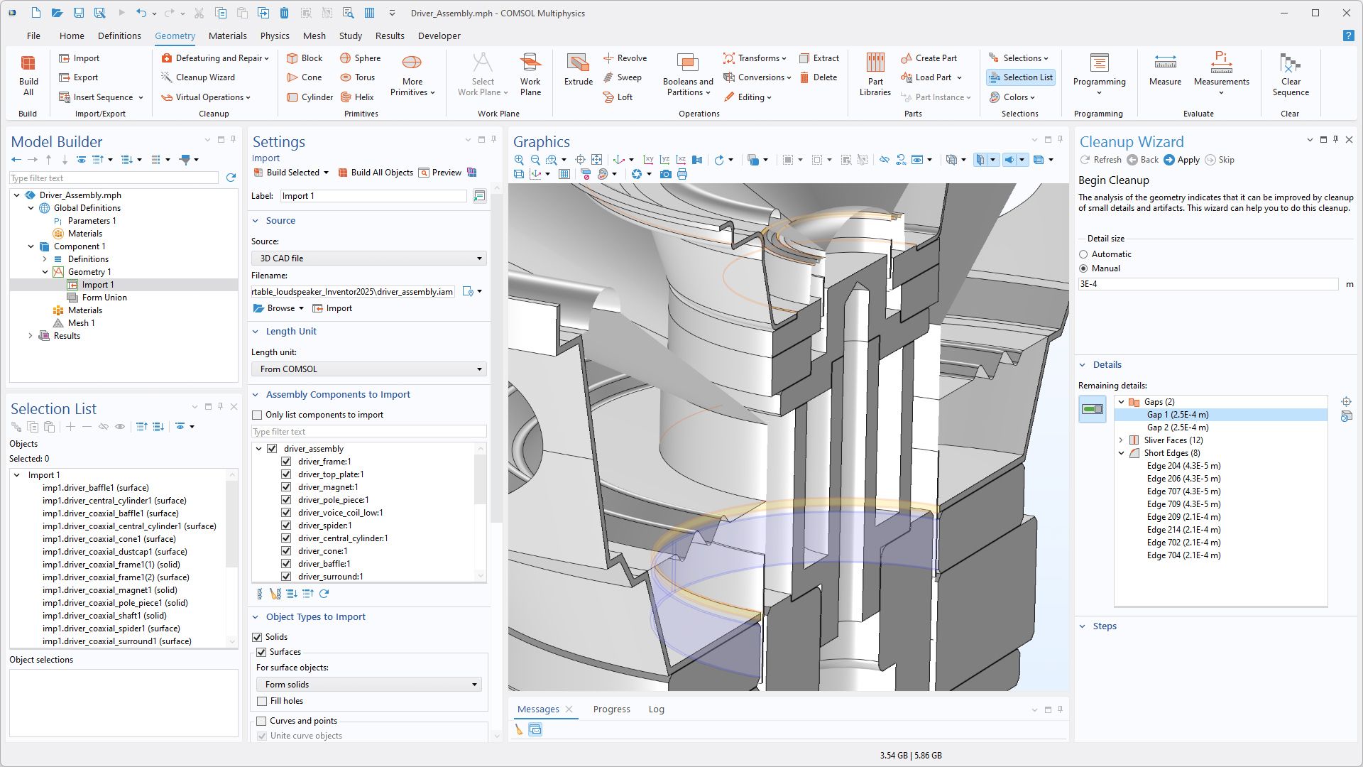
Verbesserungen von Geometry Cleanup
Die Geometrieanalyse in der Funktionalität Geometry Cleanup wurde verbessert, um kleine geometrische Merkmale zuverlässiger zu erkennen und bei Geometrien mit vielen Details eine bessere Leistung zu erzielen. Kleine Details in der Geometrie, wie Lücken, dünne Bereiche, schmale Flächenbereiche, kleine Flächen, Splitter und kurze Kanten, werden automatisch erkannt und entfernt, um ein hochwertiges Netz für die Simulation zu erzeugen. Die folgenden Tutorial-Modelle veranschaulichen diese Verbesserungen:
Leistungsverbesserungen
Boolesche Operationen in 3D, die viele Flächenüberschneidungen beinhalten, können nun dank verbesserter Multicore-Unterstützung für den COMSOL-Geometriekernel um ein Vielfaches schneller durchgeführt werden.
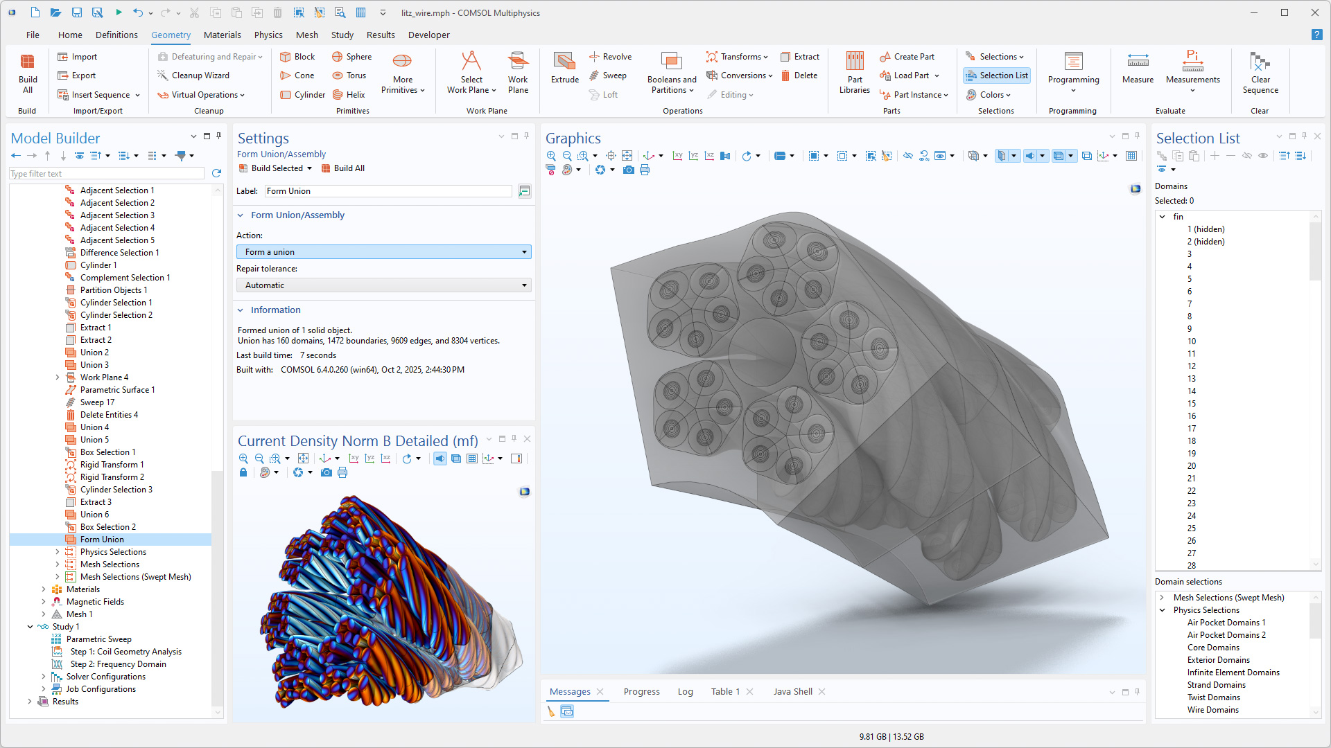
Die Erzeugung von Rand-Paaren für gestapelte extrudierte Objekte erfolgt nun deutlich schneller, wenn die Finalisierungsmethode Form an assembly verwendet wird. Diese Verbesserung ist besonders nützlich für geschichtete Leiterplatten und MEMS-Bauelemente, kann jedoch auf jede Geometrie angewendet werden, die in z-Richtung gestapelte extrudierte Objekte enthält.
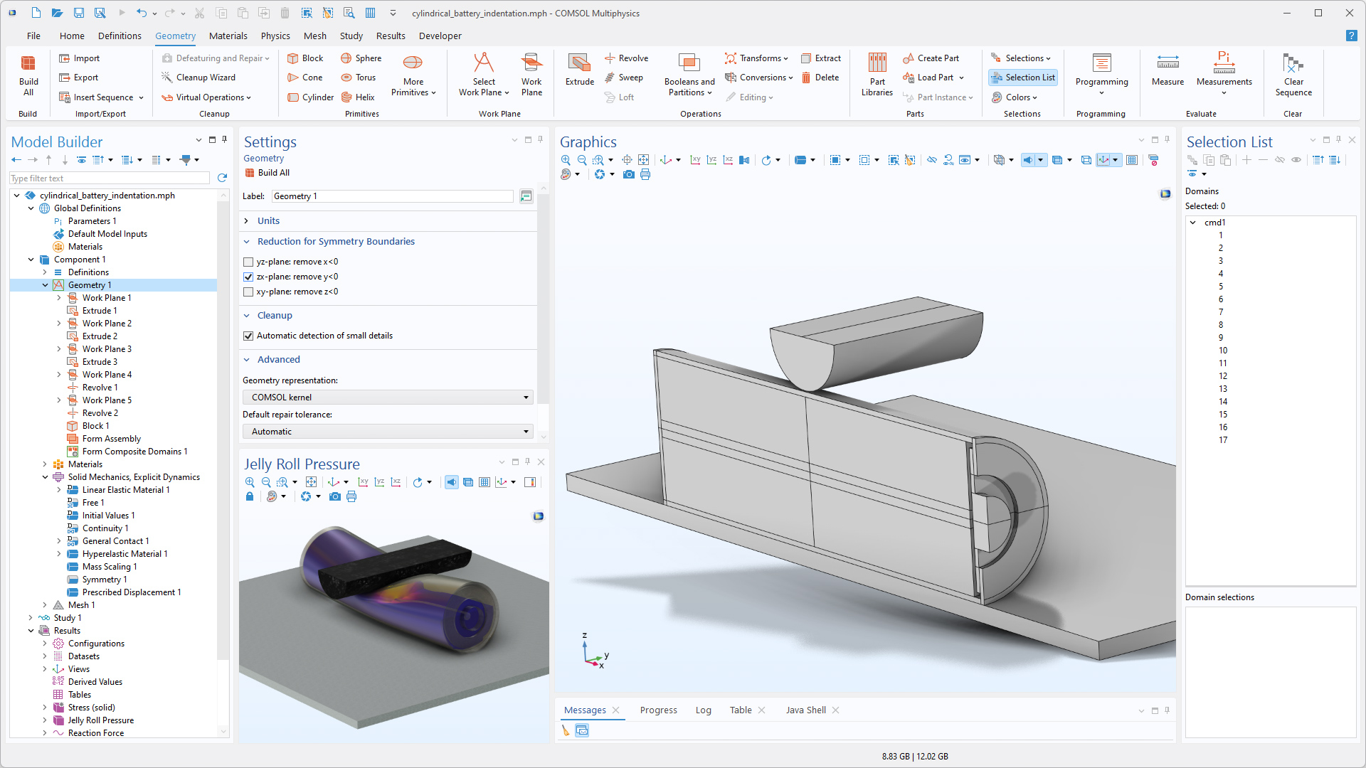
Reduktion der Geometrie in Bezug auf Symmetrieebenen
Die Geometrie kann nun automatisch in Bezug auf Symmetrieebenen reduziert werden. Durch Auswahl der entsprechenden Option im Einstellungsfenster des Knotens Geometry wird die Geometrie auf einer Seite der ausgewählten Symmetrieebenen entfernt. Bisher konnte diese Art der Symmetriereduktion nur durch manuelles Subtrahieren eines Blocks mithilfe boolescher Operationen erreicht werden. Diese Aktualisierung ist in den folgenden Tutorial-Modellen zu sehen:
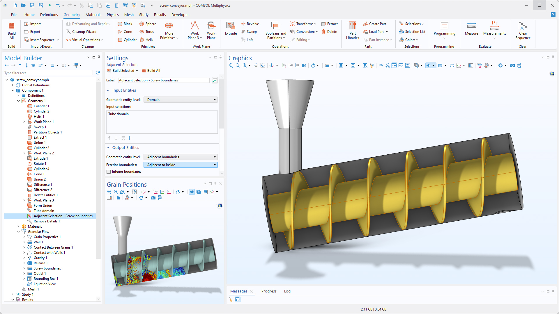
Verbesserte Auswahl
Das Feature Adjacent Selection unter Geometry sowie die Auswahlfunktionen Adjacent und Explicit unter Definitions umfassen neue Optionen. In der Abbildung unten grenzen die Ränder einer Schraube an einen Hohlraum im Rohrbereich und können mit der neuen Option Adjacent to inside ausgewählt werden. Darüber hinaus ermöglicht die neue Option Adjacent to outside die automatische Auswahl der Außenränder von Gebieten.